Nokia N900 has a bunch of interesting sensors and actuators. This post explain how to read the internal sensors (e.g. accelerometer) and write the actuators (e.g. vibration motor) by accessing sysfs in X Terminal application. Details can be found in Maemo wiki pages
Interrupts are interruptions from the main program flow triggered by some event. Interrupts are not supported by BASIC Stamp but Arduino can support it by including a library. AVR MacPack (AVR-GCC) also can support it by including <avr/interrupt.h>. Interrupts is very useful function because you don’t have to listen to the external event all the time in your code. If you assign the external event as interrupts, AVR jumps to particular function when the event happens and returns to current location of the code.
Bit operations are used when interfacing with digital out such as switching pins On/Off. Programming with bit operations enable following functions to control digital out.
Switching pins on (for example, turning on LED)
Switching pins off (for example, turning off LED)
Toggling pins (for example, Turning of LED if it is on and vice versa)
Digital and analog pins are controlled by accessing bits. Arduino NG Diecimila has Atmel Atmega8 on board and Atmega8 has two digital ports and one analog (digital to analog converter) port. This post describes Pin assign between Arduion and Atmega8. It also describes location of bits assigned to specific ports.
As Arduino has Atmel chip on board, you can also program code with C on your Mac. Softwares for the developing environment are all free. Programming with C looks more complicated but still all logic are the same as Arduion IDE and you can even create more functions with C. Once you have managesd to run your C language code on Arduio, you can also flash the code to other smaller or more powerful Atmel chips. This post describes how I as Mac user managed to write a code to blink LED on Arduion board.
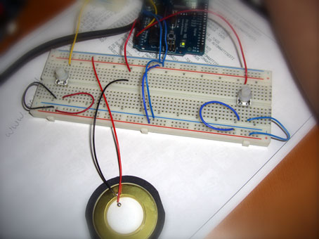
PBasic code for Ping))) Ultrasonic Sensor looks very simple.
BASIC Stamp PBasic code:
pPing PIN 7 ‘ 7 pin connects to SIG pin of the PING)))
wTime VAR WORD ‘ declaring wTime as a variable
cTrigger CON 5 ‘ trigger pulse = 10 uS for BS2
DO ‘ repeat between DO – LOOP PULSOUT pPing, cTrigger ‘ send a command to Ping))) PULSIN pPing, 1, wTime ‘ receive a value from Ping)))
DEBUG DEC5 wTime, CR ‘ send the value to computer
PAUSE 100 ‘ stop for 100 milliseconds
LOOP
If you are not familiar with BS, you can only look at Pulsin and Pulsout. Once BS sends a Pulse for a certain period. The period seems 50µs. The Ping))) sensor send back the value after that.
Pulseout command:
PULSOUT Pin, Period
Pin is a variable/constant/expression (0 – 15) that specifies the I/O pin to use. This pin will be set to output mode.
Period is a variable/constant/expression (0 – 65535) that specifies the duration of the pulse. The unit of time depends on the microcontroller. in my case, a unit is 10µs.
PULSIN Pin, State, Variable
Pin is a variable/constant/expression (0 – 15) that specifies the I/O pin to use. This pin will be set to output mode.
State is a variable/constant/expression (0 – 1) that specifies whether
the pulse to be measured is low (0) or high (1). A low pulse begins
with a 1-to-0 transition and a high pulse begins with a 0-to-1
transition.
Variable is a variable (usually a word) in which the measured pulse duration will be stored.
f you want to simulate this on Max/MSP via Maxduino by Marius Schebella and Arduino, You can download a PDF about the PING))) from Parallax site. Page 3 would be helpful to understand the pulse.
Apr 11, 2007Comments Off on Controlling servos with Motion Sensor
At the beginning me and Linus Roune both had a go at controlling Servos with some sort of data we would get form a sensor. Linus got into some heavy stuff with Arduino I went to look for solution using Basic Stamp.
The servos we had were Parallax (Futaba) Servos so hooking them with Basic Stamp was easy, and I found the code on the web. What I didn’t pay attention to was the difference between Standard and Continuous Rotation type of servo.
It is possible to make Arduino and Pure Data communicate with each other so that one doesn’t have to program Arduino with it’s own programming language (which is called Arduino).
The Arduino (build 0007) analogue output pins (PWM 9-11) have a frequency of approximately 30769 Hz. According to the Parallax documentation (http://www.parallax.com/dl/docs/books/edu/roboticsservomod.pdf) the low time for a pulse train can be between 20-40ms which means that the Arduino pulse is in the range. However, to be consistent with the BS board the frequency can be lowered by the following code =>