Feb 18, 2007
Arduino & Pure Data
INSTALL PROCESS
It is possible to make Arduino and Pure Data communicate with each other so that one doesn’t have to program Arduino with it’s own programming language (which is called Arduino).
However the frimware that Arduino needs to communicate with Pure Data must be first uploaded to Arduino board and this has to be done in Arduino programming environment. There is a package called Pduino which includes required Arduino frimware and some Pure Data examples and this package can be found from Hans-Christoph Steiner’s web page. The direct address to package is here :
http://at.or.at/hans/pd/Pduino-0.2.zip
In this package there is folder called Pd_firmware and in that folder is file called Pd_firmware.pde. This file is Arduino programming language file which must be opened and uploaded to Arduino by using Arduino programming environment. After this Arduino environment can be closed because Pure Data can communicate straight with Arduino.
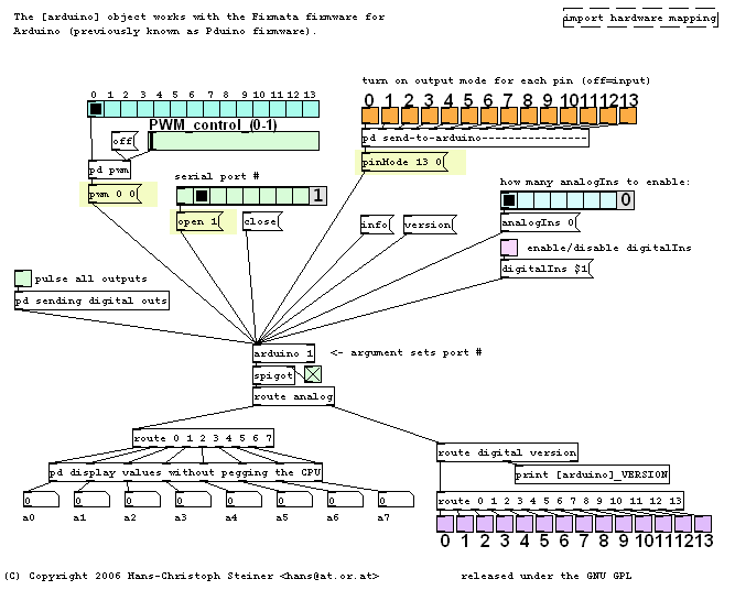
Package also includes Pure Data file called arduino-test.pd which is good place to start to get to know how Pure Data and Arduino communicate.
ARDUINO -OBJECT
In the middle of the example patch there is object called arduino. This object handles the data flow between Arduino and Pure Data and control objects are all connected to this arduino -object.
HOW TO CHOOSE A SERIAL PORT
First thing to do in Pure Data is to choose which serial port the Arduino is going to use. In example patch this can be done by green radio button control which is located a bit up and left from the middle of the patch. This radio button control has 8 (0 – 7) different choices. In my Mac OS X the right serial port was 2. Under the radio button control there is also Close -message and by clicking this message one can quit communication between Arduino and Pure Data.
ARDUINO’s PINS
Arduino has two kinds of pins, 6 analogue and 13 digital pins.
All 6 analogue pins can only serve as input pins which means that they get information from analogue sensors and transmit that information to Pure Data.
All 13 digital pins can serve as digital inputs, digital outputs and analogue outputs. This means that if one is controlling analogue device from Pure Data, the device must be attached to Arduino’s digital pins. It is good to know that pin 13 has built-in resistor which sometimes causes some voltage to “disappear” strangely.
ANALOGUE INPUT
If one wants to use analogue input pins, the first thing to do in Pure Data after choosing serial port, is to choose how many analogue pins one wants to use. This can be done by choosing wanted number of analogue inputs from blue radio button control object which is located to up and right from the middle of the example patch. If zero is chosen, no input will be received from analogue inputs. When one chooses the amount of analogue inputs, number boxes at the down left of the example patch start to present incoming sensor information. All these input flows can be stopped by unchecking green check box right under the arduino -object.
MODES OF 13 DIGITAL PINs
At the upper right corner of the example patch there is line of orange checkbox control objects. These objects define modes of 13 digital pins. They can serve either as input pins or as output pins. By checking one of the checkboxes one defines the chosen pin to be output pin and by unchecking one of the boxes one defines chosen pin to be input pin. It is good to remember that in this phase there is no way to define whether output going to one of these pins is analogue or digital.
DIGITAL INPUT
After one has defined which digital pins are used as inputs, one can activate digital inputs by checking pink checkbox located right and a bit up from the middle of the example patch. The checkbox is also under the radio button control object of analogue pins. After digital inputs are enabled, there should be some activity at the down right corner of the example patch. Down there are 13 purple checkboxes which show if value one has been transmitted trough digital input pin to Pure Data.
DIGITAL OUTPUT
Left from middle of the example patch there is green checkbox which sends pulse to all digital outputs. In this example patch there is no other way to send digital output but this pulse. However by examining arduino -object more closely one can find out how to send value one or zero to certain digital output.
ANALOGUE OUTPUT
At upper left corner of the example patch there is blue radio button control object which defines to what analogue output pin one is going to send some voltage. The amount of voltage can be controlled by slider right below the radio button control object. Of course the mode of the pin to which voltage is send to, must be output.
Tuomo Tarkiainen & Kalle Mäntsälä

Hello!
Thanks fot the good instructions to get familiar with arduino and pd.
In your example the arduino-test.pd files layout are missing some modules/objets/components compared to one which was downloaded from
http://at.or.at/hans/pd/objects.html
at 31.10.2009
So the intructions are not completely followable. Is there other arduino-test.pd files available,? Or should you update the instructions (if you would like to not let your site get expired).
Thank you anyway this was helpfull in any case.
thank you very much for this good explanation, i was looking to it so long to familiarize with PDUINO object’s
i have a question, dose the “arduino” object’s sends the message through serial port automatically while receiving data from PD interfaces ??