May 5, 2011
Course material: Arduino connected to open Frameworks
This post describes the way to establish communications between open frameworks on Mac OX10.6 and Arduino. The code using it is created on Xcode developing software. It uses ofArduino library which let you control Arduino directly from Xcode. Although the open frameworks also provide a generic Serial protocol. In this case, you need to create own Arduino code using Arduino IDE software.
Required hardware
- Arduino board
- USB A-B cable
- Breadboard
- Jumper wires
- Mac with later than OS 10.6
Required software
- Xcode
- openFrameworks library for Mac
- Arduino IDE
- USB driver for Arduino (This usually comes with the Arduino IDE)
- Firmata test app
Examples from media lab students
Quick introduction of Arduino IDE
openFrameworks Arduino class resemble actual Arduino code. Let’s take a look inside Arduino.
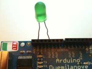
- Connect a LED to Arduino Pin 11 and GND pin as you see above. LED has polarity. The longer leg should go to the pin 11.
- Connect your Arduino with your Mac.
- Open Arduino IDE
- Create new file. File > New
- Choose an appropriate port number. Port > /dev/cu.usbserial – ****
- Copy and paste the following example codes.
int ledPin = 11;void setup() {//Configures the specified pin to behave either as an input or an output.pinMode(ledPin, OUTPUT);}void loop() {digitalWrite(ledPin, HIGH);//Pauses the program for the amount of time in miliseconds.delay(2000);digitalWrite(ledPin, LOW);delay(1000);}
- Upload the code to Arduino. File > Upload to I/O Board.
- Led will flash repeatedly.
- Change integers in the delay functions above.
- As you see above, setup runs only once when Arduino is powered or reset. Loop is running repeatedly until you unplug power, USB or press a reset button.
Test run without openFrameworks
This test run checks if your Arduino is communicating with your Mac based on specific protocol. We don’t need openFramework in this run.
- To let Xcode to control Arduino, it need to have a certain firmware in the Arduino. It is called Firmata. Firmata firmware in one of default example sketch of the Arduino IDE.
- Open Arduino IDE > File > Examples > Firmata > StandardFirmata
- Download Firsmata Test application
- Put Pin 11 Output and click Low to change it to High. You made a successful run if you can control the LED!! You can ignore that another LED with RX also flashess. The LED flashes when Arduino receives a signal from serial port.
Setup openFrameworks and Xcode
My colleague Nuno Correia from Media lab Helsinki has made an excellent tutorial how to create an app using openFrameworks on Mac OSX. Please read his tutorial first if you are new to C++ language and Xcode.
Test run with openFrameworks
In this time, you can use the openFrameworks to communicate with Arduino. You don’t need any electronic component but Arduino connected to your Mac.
- Download firmataExample and unzip.
- Move the project directory under apps/ of your downloaded openFrameworks directory.
- Open firmataExample.xcodeproj.
- After the project file is open in the Xcode, open “testApp.cpp” under src directory.
- Find a line in the testApp.cpp says “ard.connect(“/dev/tty.usbserial-A9007V8O”, 57600);” and repace the string starts with “tty.usb…” with the port number you used in Arduino when uploading.
- Let’s code the rest of them together!
Understanding breadboard
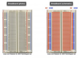
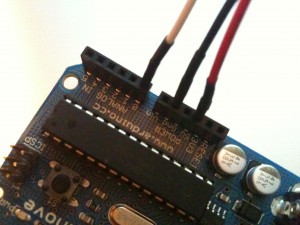
As Arduino does’t have any space to assemble other electronic components directly, so called breadboard is a great tool to do that. You can easily insert and take out components without soldering therefore it has holes in grid. The holes are connected by following a certain rule. See the figures below. The left one show schematic view of the breadboard. the red and blue lines show the connectivity between holes. 5V always goes to 5V pin on Arduino. GND does to GND pin.
Assemble Electronics
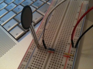
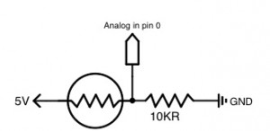
- Force sensitive sensor
- 1000 ohm resistor
- LED (Keep the LED connected to pin 11)
- jumper wires
Dimming LED controlled by pressure or bend
- There is no change on your breadboard and Arduino.
- Let’s write additional code together!
Sensing with other components by using analog input
You can use other sensors as follow. You don’t need to change the circuit. You just need to replace Force sensitive sensor with another sensor. These sensors don’t have any polarity.
- Flex sensor
- Photoresistor
- Potentiometer
- Piezo microphone
