Aug 6, 2009
UCIT: Vibrotactile radar using two PING))) ultrasonic sensors
This is quite simple practice work build for the UCIT Interaction Design with Electronics workshop 2009 held by Michihito Mizutani. The work consists of parts. 1) BS2 reads the distance information from two PING))) ultrasonic sensors and sends them through a serial port. 2) A PC running a dedicated PD (Pure Data, http://puredata.info/) patch processes the data and sends audio signals to left and/or right channels depending on the situation. 3) The audio output is then amplified and played through two C-2 vibrotactile voice-coil actuators. 4) The PD patch redirects the distance information to another PC via WLAN TCP connection where it’s been visualized.
Vibrotactile radar using two PING))) ultrasonic sensors from Jussi Rantala and Jukka Raisamo from Univertsity of Tampere, Finland.
The four parts of the practice work are described below more precisely with respective source codes and pictures.
Note that all the patches and other source files plus pictures can be downloaded from here
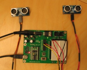
1) BS2 board with two PING))) ultrasonic sensors.
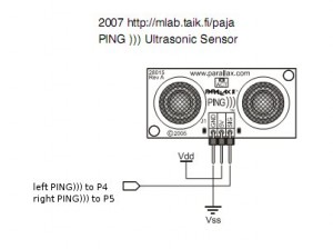
Below can be seen the very simple schema about connecting the PING))) sensors to BS2 board. One input pin per sensor is used to request & receive the distance information from the sensor. Vdd is the default 5 V.
Schematic figure of the PING))) -> BS2 hook-up.
The BS2 code is attached below.
‘{$STAMP BS2}
‘{$PBASIC 2.5}
‘ 2009 for mlab.taik.fi/paja
‘ Jukka Raisamo & Jussi Rantala
‘ Ultrasonic Navigator using 2 x PING))) Ultrasonic sensor
‘ —[ I/O Definitions ]—
pPingL PIN 4 ‘ PING ))) input left
pPingR PIN 5 ‘ PING ))) input right
‘ —[ Variables ]—
rawDistL VAR Word ‘ raw measurement (left distance in time)
rawDistR VAR Word ‘ raw measurement (right distance in time)
cmL VAR Word ‘ distance in cm, left
cmR VAR Word ‘ distance in cm, right
‘ —[ Constants ]—
#SELECT $STAMP
#CASE BS2, BS2E
cTrigger CON 5 ‘ trigger pulse = 10 uS
cScale CON $200 ‘ raw x 2.00 = uS
#CASE BS2SX, BS2P, BS2PX
cTrigger CON 13
cScale CON $0CD ‘ raw x 0.80 = uS
#CASE BS2PE
cTrigger CON 5
cScale CON $1E1 ‘ raw x 1.88 = uS
#ENDSELECT
cRawToCm CON 2257 ‘ 1 / 29.034
‘ the speed of sound at sea level
‘ If one wants to calibrate the distance to prevailing circumstances
‘ use the formula below.
‘ speed of sound formula: C_air = 331.5 + (0.6 * T_c) m/s
‘ —[ Main Code ]—
Main:
DO
PAUSE 5
GOSUB ReadPingL
cmL = rawDistL ** cRawToCm ‘ convert to centimeters
PAUSE 5
GOSUB ReadPingR
cmR = rawDistR ** cRawToCm ‘ convert to centimeters
‘ Sends distance info to serial port
‘ Format: [distance left] [distance right] [CR=ASCII 13]
DEBUG DEC3 cmL, DEC3 cmR, CR
LOOP
END
‘ —[ Subroutines ]—
ReadPingL:
‘ PULSOUT Pin, Duration
‘ Duration: specifies the duration of the pulse. (BS2: a unit = 2us)
PULSOUT pPingL, cTrigger
‘ PULSIN Pin, State, Variable
‘ State: Specifies whether the puse to be mesured is low(0) or high(1)
‘ Variable: the measured pulse duration will be stored.
PULSIN pPingL, 1, rawDistL
rawDistL = rawDistL */ cScale ‘ convert to uS
rawDistL = rawDistL / 2 ‘ remove return trip
RETURN
ReadPingR:
PULSOUT pPingR, cTrigger
PULSIN pPingR, 1, rawDistR
rawDistR = rawDistR */ cScale
rawDistR = rawDistR / 2
RETURN
Picture of the BS2 setup.
2) A Pure Data (PD from now on) patch receives the trains of eight decimal numbers (DEC3 distance left, DEC3 distance right & CR) and parses the two distance values based on that.
The main PD patch (ultrasonic_navigator.pd) is shown in a picture below. That and other relevant material can be downloaded from here.
A PD patch that is entry point for sensor data processing.
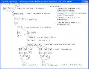
The patch sends parsed values to three other patches that determine the vibrotactile feedback balance (distance_feedback_balance.pd), the rhythm of the feedback (distance_feedback_rhythm.pd), as well as redirects the information via TCP connection to remote computer to be visualized (distance_send_data.pd).
The flags determined by the balance and rhythm patches define the feedback signal driven to the left and right audio channels by the output patch (distance_output.pd).
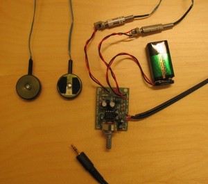
3) The audio output is amplified and played through two dedicated C-2 vibrotactile voice-coil actuators (manufactured by Engineering Acoustics, Inc.). The amplifier is a standard 1W stereo audio amplifier build from a kit using a 9 V battery as a power source. Picture of the output setup can be seen below.
Picture of the output setup with amplifier, two C-2 actuators and a 9 V battery.
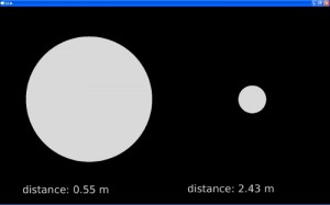
4) A dedicated PD patch (distance_send_data.pd) redirects the distance information to another PC via WLAN TCP connection. The current solution uses a standard FTP port (21) that is often open in also firewalled networks. Yet another set of PD patches (located in ultrasonic_navigator_gui folder) visualize the distances on a screen for demo purposes. A sample picture of the PD screen is shown below.
An user interface visualizing the distance information.
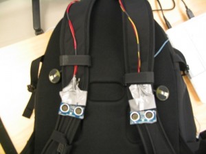
FINALLY, some pictures of the final working prototype integrated into a backpack (we had some mysterious power- off issues with both of our laptops when stucked inside the backpack, so we needed to held one in our hand).
Integration: two PING))) sensors attached on top of the shoulder-strap and two C-2 actuators that are attached under the straps.