Feb 6, 2007
Experiments in electromagnetic induction
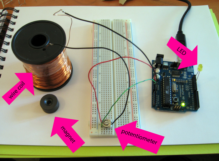
Our first working test setup visualised electromagnetic induction by changing the intensity of a LED. We routed the +5V power through a potentiometer into a wire coil and from there the to the analog input pin of the Arduino NG. The changes in the magnetic field inside and around the coil(like when waving a magnet near the coil) induce small voltages in the coil which show up in the readout of the analog pin.
Minimum and maximum voltage values and the difference between these are computed for 100ms intervals. The difference is used as a measure of the amount of voltage fluctuation and translated into the intensity of the LED.
— Jan & Miska

what is the size of the wire used to this experiment?
kindly give me the info for our research…
tnx^^
The size of wire is not very significant, almost any size will work. The magnitude of the induced voltage depends on the number of turns in the coil: more turns, larger voltage.
what is the material used in the wire to be coiled?…i mean that circular tubelike stuff used in winding the wire?
The coil is traditionally copper.
Thank you for the nifty experiment utilizing an arduino!