Apr 11, 2009
Atmel Atmega8 (Arduino NG) Digital I/O pin register
Digital and analog pins are controlled by accessing bits. Arduino NG Diecimila has Atmel Atmega8 on board and Atmega8 has two digital ports and one analog (digital to analog converter) port. This post describes Pin assign between Arduion and Atmega8. It also describes location of bits assigned to specific ports.
With AVR-GCC, digital pins need to be declare if they are output or input mode before pins create any signal.
#include <avr/io.h>
#include <util/delay.h>
int main(void){
DDRB = (1<<PB5); // make Arduino Pin 13 (Atmega8 PortB pin 5) an output
for(;;){
char i;
for(i = 0; i < 10; i++){
_delay_ms(30); // max is 262.14 ms / F_CPU in MHz
}
PORTB = (1<<PB5); // Put Arduino Pin 13 (Atmega8 PortB pin 5) HIGH
}
return 0;
}
Pin assign in Arduion NG and Atmega8
| Arduino Pin | 0 (RX) |
1 (TX) |
2 | 3 | 4 | 5 | 6 | 7 | 8 | 9 (PWM) |
10 (PWM) |
11 (PWM) |
12 | 13 |
|---|---|---|---|---|---|---|---|---|---|---|---|---|---|---|
| Atmega8 Pin (Port + Pin) | PD0 | PD1 | PD2 | PD3 | PD4 | PD5 | PD6 | PD7 | PB0 | PB1 | PB2 | PB3 | PB4 | PB5 |
Atmega8 has Port B and D as digital I/O. Port C is for digital to analog converter.
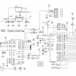
Arduino NG schematic
DDRB Direction pin register (0 -> input, 1 -> output)
| Bit | 7 | 6 | 5 | 4 | 3 | 2 | 1 | 0 |
|---|---|---|---|---|---|---|---|---|
| —– | —– | DDB5 | DDB4 | DDB3 | DDB2 | DDB1 | DDB0 | |
| Arduino Digital Pin | 13 | 12 | 11 | 10 | 9 | 8 | ||
| Read/Write | R | R | R/W | R/W | R/W | R/W | R/W | R/W |
| Initial value | 0 | 0 | 0 | 0 | 0 | 0 | 0 | 0 |
DDRD Direction pin register (0 -> input, 1 -> output)
| Bit | 7 | 6 | 5 | 4 | 3 | 2 | 1 | 0 |
|---|---|---|---|---|---|---|---|---|
| DDD7 | DDD6 | DDD5 | DDD4 | DDD3 | DDD2 | DDD1 | DDD0 | |
| Arduino Digital Pin | 7 | 6 | 5 | 4 | 3 | 2 | 1 | 0 |
| Read/Write | R/W | R/W | R/W | R/W | R/W | R/W | R/W | R/W |
| Initial value | 0 | 0 | 0 | 0 | 0 | 0 | 0 | 0 |
If DDxn is written logic one, Pxn is configured as an output pin. If DDxn is written logic zero, Pxn is configured as an input pin.
PORTB register (Digital I/O)
| Bit | 7 | 6 | 5 | 4 | 3 | 2 | 1 | 0 |
|---|---|---|---|---|---|---|---|---|
| —– | —– | PORTB5 | PORTB4 | PORTB3 | PORTB2 | PORTB1 | PORTB0 | |
| Arduino Digital Pin | 13 | 12 | 11 | 10 | 9 | 8 | ||
| Read/Write | R | R | R/W | R/W | R/W | R/W | R/W | R/W |
| Initial value | 0 | 0 | 0 | 0 | 0 | 0 | 0 | 0 |
PORTD register (Digital I/O)
| Bit | 7 | 6 | 5 | 4 | 3 | 2 | 1 | 0 |
|---|---|---|---|---|---|---|---|---|
| PORTD7 | PORTD6 | PORTD5 | PORTD4 | PORTD3 | PORTD2 | PORTD1 | PORTD0 | |
| Arduino Digital Pin | 7 | 6 | 5 | 4 | 3 | 2 | 1(TX) | 0(RX) |
| Read/Write | R/W | R/W | R/W | R/W | R/W | R/W | R/W | R/W |
| Initial value | 0 | 0 | 0 | 0 | 0 | 0 | 0 | 0 |
If PORTxn is written logic one when the pin is configured as an input pin, the pull-up resistor is activated.
If PORTxn is written logic one when the pin is configured as an output pin, the port pin is driven high (one).
PINB register (Digital In)
| Bit | 7 | 6 | 5 | 4 | 3 | 2 | 1 | 0 |
|---|---|---|---|---|---|---|---|---|
| PINB7 | PINB6 | PINB5 | PINB4 | PINB3 | PINB2 | PINB1 | PINB0 | |
| Arduino Digital Pin | 7 | 6 | 5 | 4 | 3 | 2 | 1(TX) | 0(RX) |
| Read/Write | R | R | R | R | R | R | R | R |
| Initial value | N/A | N/A | N/A | N/A | N/A | N/A | N/A | N/A |
PIND register (Digital In)
| Bit | 7 | 6 | 5 | 4 | 3 | 2 | 1 | 0 |
|---|---|---|---|---|---|---|---|---|
| ? | ? | PIND5 | PIND4 | PIND3 | PIND2 | PIND1 | PIND0 | |
| Arduino Digital Pin | 13 | 12 | 11 | 10 | 9 | 8 | ||
| Read/Write | ? | ? | R | R | R | R | R | R |
| Initial value | ? | ? | N/A | N/A | N/A | N/A | N/A | N/A |
These ports are used to read pin status.

