Apr 13, 2009
Control LED by pressing button (using interrupts function in AVR)
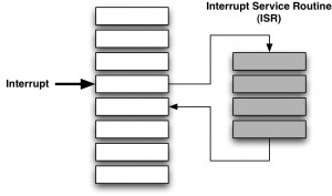
Interrupts are interruptions from the main program flow triggered by some event. Interrupts are not supported by BASIC Stamp but Arduino can support it by including a library. AVR MacPack (AVR-GCC) also can support it by including <avr/interrupt.h>. Interrupts is very useful function because you don’t have to listen to the external event all the time in your code. If you assign the external event as interrupts, AVR jumps to particular function when the event happens and returns to current location of the code.

There are two types of interrupts.
- Trigger on rising edget, falling edget, any change or low-level: INT0 and INT1
- Triggers on toggle of pins: PC10, PC11, PC12 (Atmega8 doesn’t seem to support this feature…)
Call sei() function to enable interrupts and call cli() function to disable interrupts.
1. Trigger on rising edget, falling edget, any change or low-level: INT0 and INT1
You need to set INT0 bit in the GIMSK register and enabling the global interrupt flag with the sei() macro. You can also define mode by setting a bit in MCUCR.
GIMSK (General Interrupt Maskregister)
GIMSK is used to enable and disable individual external interrupts by setting these bits.
| GIMSK Bit | 7 | 6 | 5 | 4 | 3 | 2 | 1 | 0 |
|---|---|---|---|---|---|---|---|---|
| INT1 | INT0 | – | – | – | – | – | – |
Example code:
GICR |= 1<<INT0; // Enable INT0 External Interrupt
MCUCR (MCU General Control Register)
MCUCR is a mode that you can chose by setting bits after setting GIMSK.
| MCUCR bit | 7 | 6 | 5 | 4 | 3 | 2 | 1 | 0 |
|---|---|---|---|---|---|---|---|---|
| SRE | SRW | SE | SM | ISC11 | ISC10 | ISC01 | ISC00 |
| MCUCR Bit | Name | Meaning | Opportunities |
|---|---|---|---|
| 7 | SRE | Ext.SRAM Enable | 0=No external SRAM connected |
| 1=External SRAM connected | |||
| 6 | SRW | Ext.SRAM Wait States | 0=No extra wait state on external SRAM |
| 1=Additional wait state on external SRAM | |||
| 5 | SE | Sleep Enable | 0=Ignore SLEEP commands |
| 1=SLEEP on command | |||
| 4 | SM | Sleep Mode | 0=Idle Mode (Half sleep) |
| 1=Power Down Mode (Full sleep) | |||
| 3 | ISC11 | Interrupt control Pin INT1 (connected to GIMSK) |
00: Low-level initiates Interrupt |
| 01: Undefined | |||
| 2 | ISC10 | 10: Falling edge triggers interrupt |
|
| 11: Rising edge triggers interrupt | |||
| 1 | ISC01 | Interrupt control Pin INT0 (connected to GIMSK) |
00: Low-level initiates interrupt |
| 01: Undefined | |||
| 0 | ISC00 | 10: Falling edge triggers interrupt |
|
| 11: Rising edge triggers interrupt |
Example code:
GIMSK |= (1<<INT0); // Enable INT0 External Interrupt
MCUCR |= (1<<ISC01); // Falling-Edge Triggered INT0
sei(); // Enable Interrupts
LED is on for one second when button is pressed.
#include <avr/io.h>
#include <avr/interrupt.h>
#include <avr/signal.h>
#include <util/delay.h>
void delay(int);
int main() {
DDRB = (1<<PB5); // put PortB bit 5 as output
GIMSK |= (1<<INT0); // Enable INT0 External Interrupt
MCUCR |= (1<<ISC01); // Falling-Edge Triggered INT0
sei(); // Enable Interrupts
for(;;){
// nothing happens.
}
}
SIGNAL(SIG_INTERRUPT0) {
// this function is called when INT0 bit (PD2) is interrupted.
// You can also use INTERRUPT() function instead.
// SIG_INTERRUPT0 -> INT0 (PD2)
// SIG_INTERRUPT1 -> INT1 (PD3)
// While Button is pressed, LED is on
PORTB |= (1<<PB5); // Put PortB bit 5 HIGH
delay(1000);
PORTB &= ~(1<<PB5); // Put PortB bit 5 LOW
delay(1000);
}
void delay(int ms) {
ms /= 100;
char i;
for(i = 0; i < ms; i++){
_delay_ms(100); // max is 262.14 ms / F_CPU in MHz
}
}
There are several signal names.
- SIG_ADC (ADC conversion done)
- SIG_EEPROM_READY
- SIG_INTERRUPT0..7 (external interrupts 0 to 7)
- SIG_OVERFLOW0..3 (timer/counter overflow)
- SIG_UART0_DATA, SIG_UART0_RECV, SIG_UART0_TRANS (UART empty/receive/transmit interrupts)
2. Trigers on toggle of pins: PC10, PC11, PC12 (Atmega8 on Arduino doesn’t seem to support this feature…)
GIFR (General Interrupt Flag Register)
GIFR indicates if an interrupt has occured. the corresponding INT flag in GIRF is set to “1”. If the interrupt gets serviced (which hapens if the 1 bit and the corresponding INT bit in GIMSK register is “1). then the flag is reset.
| 7 | 6 | 5 | 4 | 3 | 2 | 1 | 0 |
|---|---|---|---|---|---|---|---|
| INTF1 | INTF0 | – | – | – | – | – | – |
Example code:
GIFR |= (1<<INT0); // Enable INT0 External Interrupt

This tutorial seems to an interesting and very simple to beginners like me.
I really appreciate this and I am now feeling comfortable with external interrupts in AVR.
Thanks a lot… 🙂