Jul 4, 2009 2
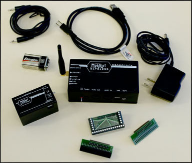
Sparkfun BlueSMiRF Silver

BlueSMiRF Silver is a bluetooth module from Sparkfun Electronics. This post describes how you can set up connectivity between your PC and BlueSMiRF.
Jul 4, 2009 2
BlueSMiRF Silver is a bluetooth module from Sparkfun Electronics. This post describes how you can set up connectivity between your PC and BlueSMiRF.
Apr 15, 2009 Comments Off on PWM by AVR-GCC
Arduino NG supports PWM with three pins – 9, 10 and 11. Those pins are assigned to Atmega8 PB1(OC1A), PB2(SS/OC1B) and PB3(MOSI/OC2) pings
PB1 (OC1A) – Arduino Pin 9
PB2(OC1B) – Arduion Pin 10
PB3(MOSI/OC2) – Arduion Pin 11
Apr 13, 2009 1
Interrupts are interruptions from the main program flow triggered by some event. Interrupts are not supported by BASIC Stamp but Arduino can support it by including a library. AVR MacPack (AVR-GCC) also can support it by including <avr/interrupt.h>. Interrupts is very useful function because you don’t have to listen to the external event all the time in your code. If you assign the external event as interrupts, AVR jumps to particular function when the event happens and returns to current location of the code.

Apr 13, 2009 Comments Off on Control LED by pressing button (digital input functions in AVR)
This post describes how to program Atmega8 on Arduino board using AVR-GCC. The program enable user to control a LED by pressing a button.
Components
Apr 11, 2009 1
Bit operations are used when interfacing with digital out such as switching pins On/Off. Programming with bit operations enable following functions to control digital out.
Apr 11, 2009 Comments Off on Atmel Atmega8 (Arduino NG) Digital I/O pin register
Digital and analog pins are controlled by accessing bits. Arduino NG Diecimila has Atmel Atmega8 on board and Atmega8 has two digital ports and one analog (digital to analog converter) port. This post describes Pin assign between Arduion and Atmega8. It also describes location of bits assigned to specific ports.
Apr 9, 2009 Comments Off on Blinking LED on Arduino NG with AVR MacPack first time
As Arduino has Atmel chip on board, you can also program code with C on your Mac. Softwares for the developing environment are all free. Programming with C looks more complicated but still all logic are the same as Arduion IDE and you can even create more functions with C. Once you have managesd to run your C language code on Arduio, you can also flash the code to other smaller or more powerful Atmel chips. This post describes how I as Mac user managed to write a code to blink LED on Arduion board.

Nov 11, 2008 Comments Off on Final demos from Designing Interaction with Electronics workshop 2008
Nov 9, 2008 Comments Off on Tools in Media Lab Helsinki
Updated on 7 November 2008
– Arduino x 20
– BASIC Stamp board (USB) x 6
– USB A-B mini cable x 9
– BASIC Stamp board (RS232) x 6
– RS232 to USB converter x 6
– Power adapter (9V) x 12
– Jumper wire box x 10
– Breadboard x 12
– Multimeter x 9
Mar 19, 2008 Comments Off on Johnny Chung Lee’s wiimote project
Feb 28, 2008 Comments Off on Absolut Quartet
Feb 25, 2008 Comments Off on Presentations from Physical Computing course at Sibelius Academy
Jan 16, 2008 Comments Off on Digital and Analog IO using MIDI
If you have following issue on your physical computing. Miditro Wireless might be a solution.
Nov 16, 2007 1
Mood shoes by Markku Ruotsalainen, Jenna Sutela and David SzauderGimme Sugar by Anna Keune and Jari SuominenGrid Shuffling by Keri Knowles and Abhigyan SinghThe Sixth Sense by Kimmo Karvinen and Mikko ToivonenHugiPet by Juho Jouhtimäki and Elise LiikalaDigital Painting Control by Juho Jouhtimäki, Kimmo Karvinen and Mikko ToivonenTwinkling Gloves by Anne Naukkarinen, Pekka Salonen and Kristine VisanenFurry Modulator by Atle Larsen and Mikko Mutanen
Nov 12, 2007 Comments Off on Argumented Reality Game
Nov 10, 2007 Comments Off on Pulse IO for Ping))) Ultrasonic Sensor
PBasic code for Ping))) Ultrasonic Sensor looks very simple.
BASIC Stamp PBasic code:
pPing PIN 7 ‘ 7 pin connects to SIG pin of the PING)))
wTime VAR WORD ‘ declaring wTime as a variable
cTrigger CON 5 ‘ trigger pulse = 10 uS for BS2DO ‘ repeat between DO – LOOP
PULSOUT pPing, cTrigger ‘ send a command to Ping)))
PULSIN pPing, 1, wTime ‘ receive a value from Ping)))
DEBUG DEC5 wTime, CR ‘ send the value to computer
PAUSE 100 ‘ stop for 100 milliseconds
LOOP
If you are not familiar with BS, you can only look at Pulsin and Pulsout. Once BS sends a Pulse for a certain period. The period seems 50µs. The Ping))) sensor send back the value after that.
Pulseout command:
PULSOUT Pin, Period
- Pin is a variable/constant/expression (0 – 15) that specifies the I/O pin to use. This pin will be set to output mode.
- Period is a variable/constant/expression (0 – 65535) that specifies the duration of the pulse. The unit of time depends on the microcontroller. in my case, a unit is 10µs.
PULSIN Pin, State, Variable
- Pin is a variable/constant/expression (0 – 15) that specifies the I/O pin to use. This pin will be set to output mode.
- State is a variable/constant/expression (0 – 1) that specifies whether
the pulse to be measured is low (0) or high (1). A low pulse begins
with a 1-to-0 transition and a high pulse begins with a 0-to-1
transition.- Variable is a variable (usually a word) in which the measured pulse duration will be stored.
f you want to simulate this on Max/MSP via Maxduino by Marius Schebella and Arduino, You can download a PDF about the PING))) from Parallax site. Page 3 would be helpful to understand the pulse.
Oct 21, 2007 Comments Off on Components can be connected to Puduino and Maxduino
I made a list of the components can be used with Pudino and Maxduino patch but not all of them have been tested. I will update when I found new components compatible with the patches.
Analog In
Digital In
Analog Out
Digital Out
Oct 16, 2007 Comments Off on HanaHana