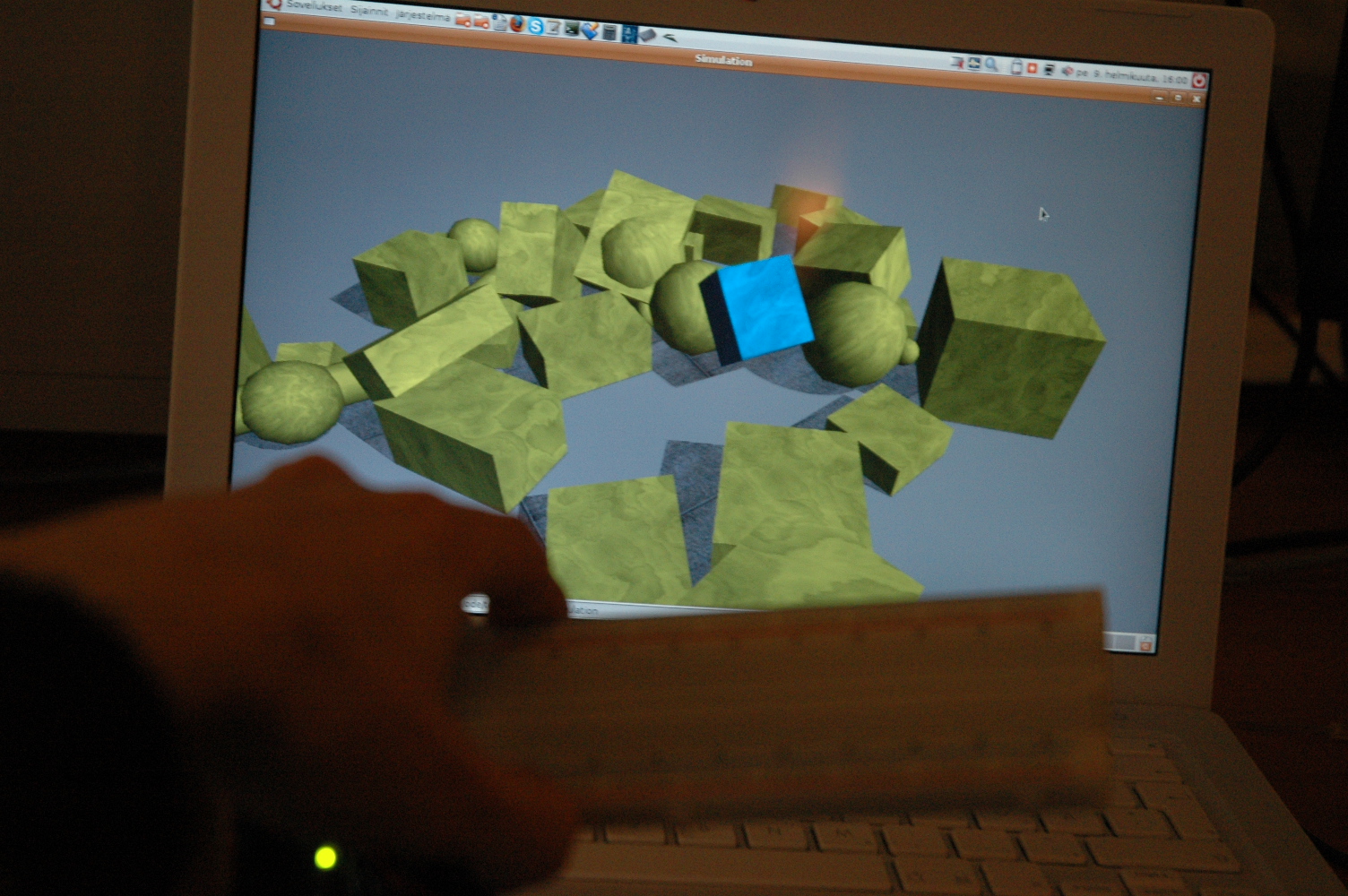
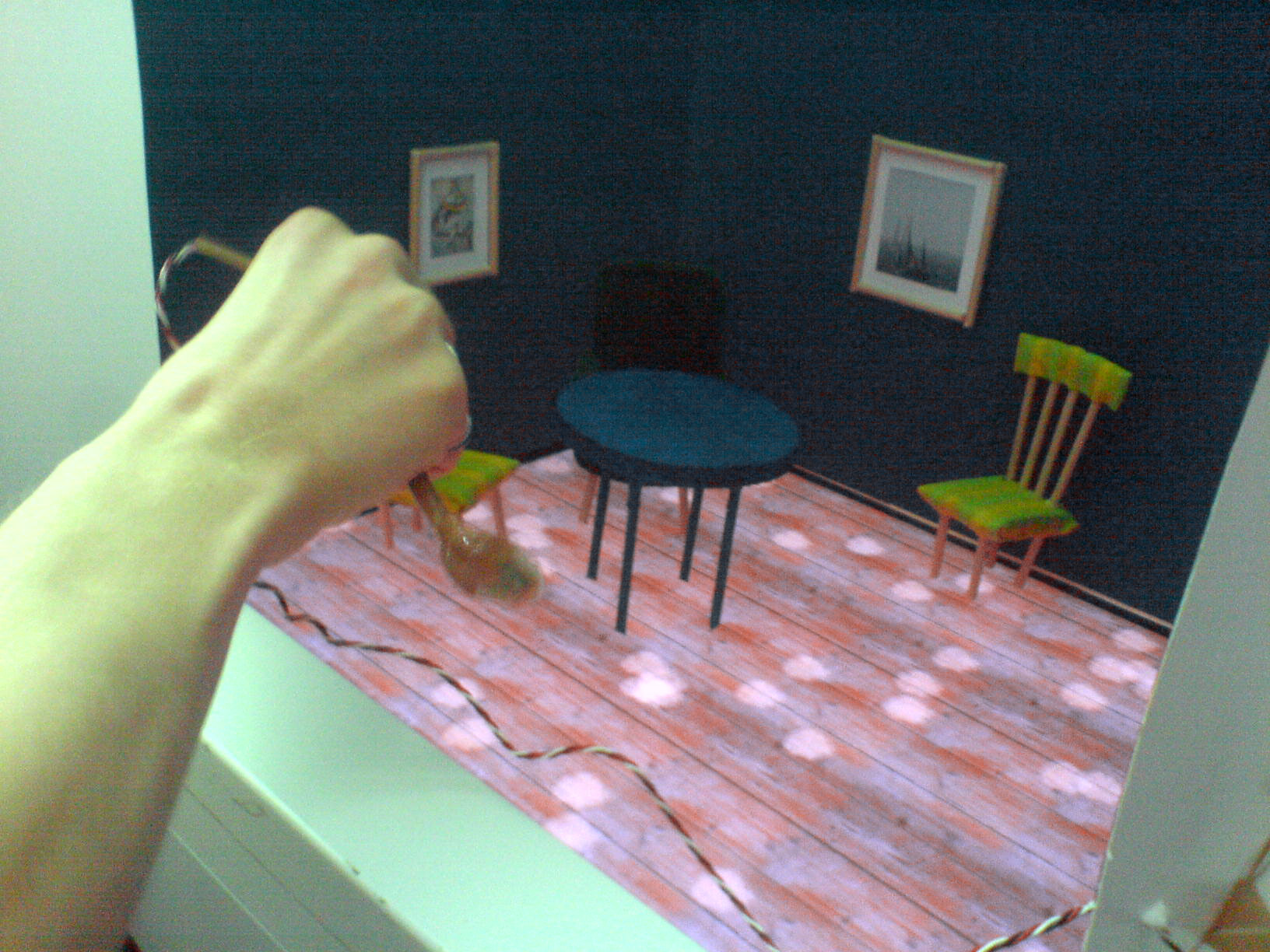
This is an educational work where children (and adults) can learn how to clean a floor with a vacuum cleaner. Inside the vacuum cleaner is a light sensor connected to Arduino-microcontroller, which is connected to Processing-software. The light sensor recognized white spots from the floor (made out of a computer display) and cleans it if one is fast enough, if not the spot get stuck.
It is possible to make Arduino and Pure Data communicate with each other so that one doesn’t have to program Arduino with it’s own programming language (which is called Arduino).
Basic idea is to ask quenstions from usen and whether the answer is right – green led will light up or if the answers wrong – red led will light up. It also counts the amount of right answers. It’s easy to continue quiz with further questions since right now there’s only one.
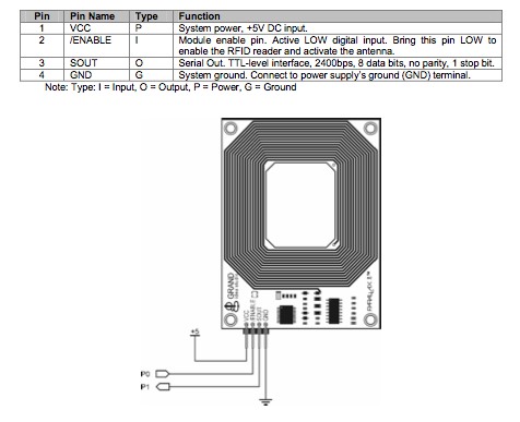
You can use Parallax RFID reader module to identify object from a large set by hiding RFID card inside it. Basically reader has two signal pins, one out and one in. First is used to enable/disable reading, second is used for reading the card identification number.
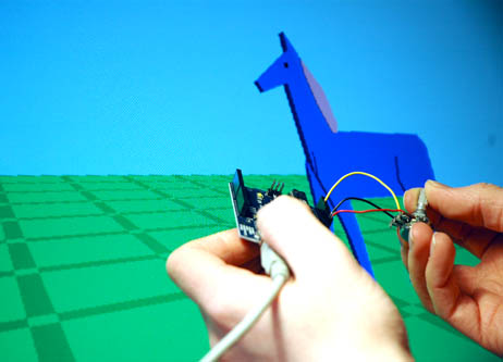
Description: This program calculates the love-potential between two people 🙂 Two touchsensors are connected to Arduino. When they are touched, the running program measures the values of the pressure-intensity during 5sec. The maximun and minimum of the measured values are saved to variables. Each second during the 5sec, the program adds the (Max – min) to a TotalSum and resets max and min. After the 5th sec. a function drawHeart is called which creates a heart on the screen calculating the size according to the TotalSum values we obtained. Got it? 🙂
Material/Software:
Arduino microcontroller & IDE Processing IDE
Flash
2 x Flexiforce touchsensor
Code/Files: Arduino/Processor/Flash-files (flash server connection and processing code by Aleksi Hyvönen and Viljo Malmberg)
This is not a very meaningful interaction, but I was playing with different in- and outputs and transferring information from one source to another.
I connected a 7-digit display to Arduino and made it display random numbers from 1 to 9.
Then I added the slidelong-touchsensor in order to create the random numbers.
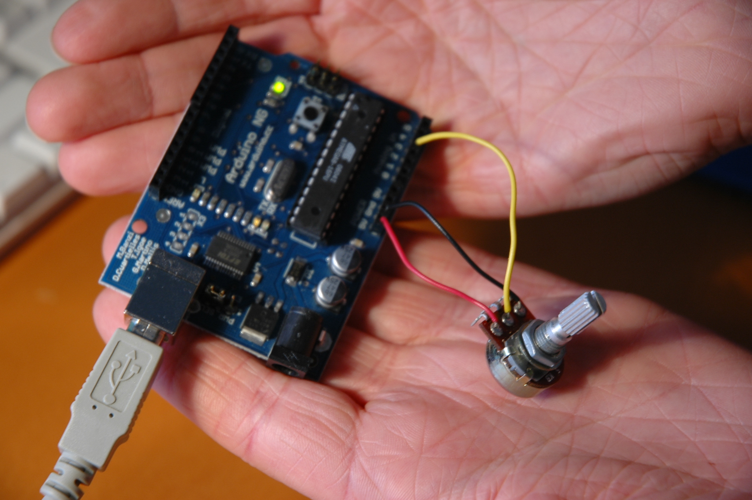
Additionally I connected a potentiometer, which determines the speed of the display. You need a resistor for the display, otherwise it gets to hot.
Creating the numbers:
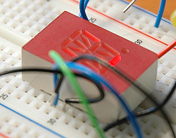
In your code have to define which LED goes to which input. I gave each LED a number from one to seven and created an array, which contains the binary codes of each number I want to display (see photo). For example number 1 is LED 1 off, LED 2 on, LED 3 on, LED 4, LED 5, LED 6, LED 7 off (in binary: 0110000). More info in the code.
Analog input: The slidelong-touchsensor gives number from 0 on one side to 1024 on the other side, depending how you connect 5V and GND.
The potentiometer gives as well numbers from 0 to 1024.
warning, will get hot. (needs resistor)
using arduino 5V the electricity is not enough? lights get dim.
other pins go LED to (-), the pin 9(sheet pin numbers are not correct?) goes to (+), on same side of pin 1 hole but on the other end. each pin will light one part of digit.
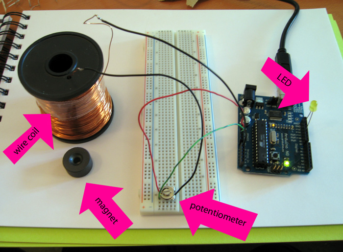
Our first working test setup visualised electromagnetic induction by changing the intensity of a LED. We routed the +5V power through a potentiometer into a wire coil and from there the to the analog input pin of the Arduino NG. The changes in the magnetic field inside and around the coil(like when waving a magnet near the coil) induce small voltages in the coil which show up in the readout of the analog pin.
Minimum and maximum voltage values and the difference between these are computed for 100ms intervals. The difference is used as a measure of the amount of voltage fluctuation and translated into the intensity of the LED.
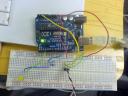
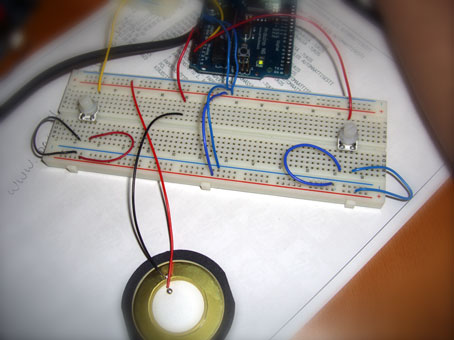
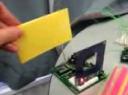
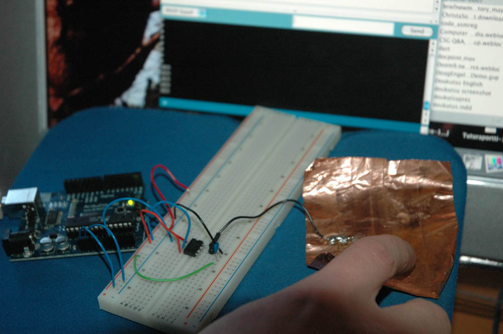
overall view: arduino, chip and wires on breadboard, touch sensor and program on background.
Touch sensor is component of many (tangible) interfaces and uses. with proper chip it will send binaric on-off (touched-intact) data or can be utilised as on-off switch. in “touch mode” the binaric value is 0 when touched, and otherwise 1. In on off mode touching will change 0 to 1 and 1 to 0. So, it works just like light switch.
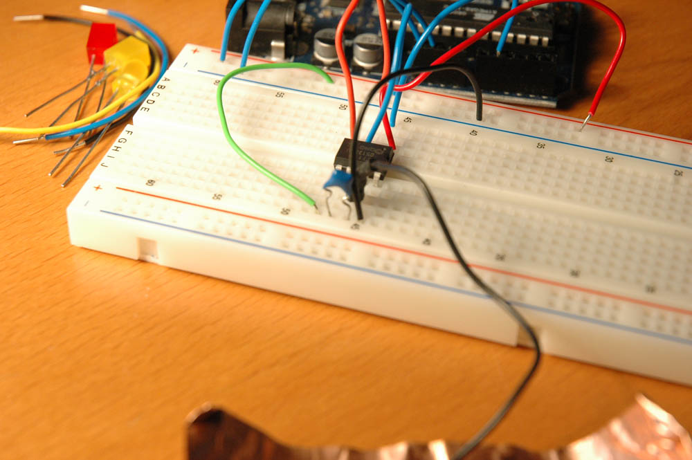
Controller chip on breadboard. Black wire goes to sensor.
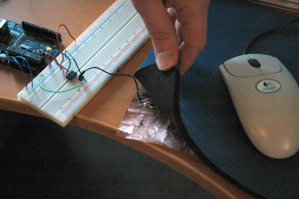
Touch component reacts from ~1 cm distance, no touching is required. It can be placed behind thin walls to react on press, or even under mouse matt:
Here the touch sensor will react if the mouse reaches the corner. Touch sensor merged with other components can create funny and interactive tangible toys and interfaces. E.g. vibrating component and touch sensor in rabbits ears could make ears wobble if one touches them. Component of creative use!
Experiments of Joonas Kiviharju and Jukka Liukkonen.


