DS1307 Real time clock can tell time to Arduino. You can turn off Arduino as a small button battery is attached to the DS1307. Once you set the right time on the DS1307, it can keep ticking up to 7 years.
TLC 5940 PWM driver can control up to 16 LEDs. You can dim each LED separately. It also allows to cascade multiple TLC 5940 PWM driver thus you can have more than 16 LEDs multiplied with the IC. As I need 60 LEDs, I am cascading 4 of them. As I understand, it communicates with SPI with a couple of additional wires. There is a Arduino library for TLC5940 which comes with good example sketches. I have attached basic schematic and Arduino code to test multiple TLC5940.
This post describes how to create PCB with Roland Modela MDX-20 mill machine using Fritzing open souce software. The instruction using Eagle is described in another post.
This is a project update for last years Designing interactions course, this could also be seen as the final report for the project for the course, even if the project in itself is still a work in progress. This project is called “Pingispöytä” and it is made by Pasi Rauhala and Niklas Kullström from the Photography department.
So What is “Pingispöytä”? The concept started from the idea of making a electronically controlled “mechanical” ball bouncer. Several different approaches arose in the beginning, with different alternatives for propulsion and ball types. In the end we decided to use solenoids and ping pong balls for the project. The idea being that a solenoid would bounce up a ping pong ball into the air at a specific defined time.
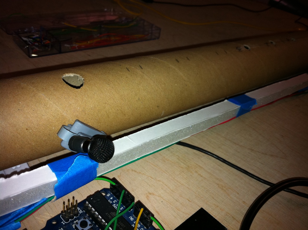
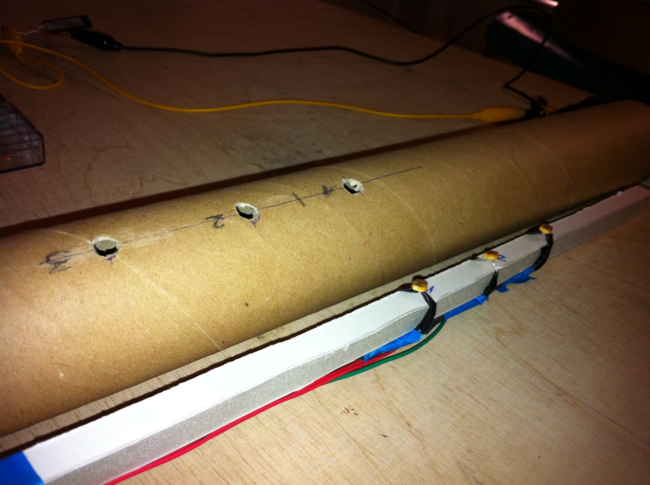
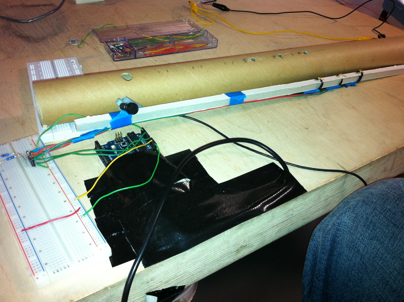
Our Reed Flute (Ney) is on its way. Photo-resistors and a small mic are attached to a backbone which will then be inserted into a hollow tube.
Mic sends audio signal thru line-in of the computer and processed in PureData. The audio is filtered out only to take certain frequencies which correspond to blowing. So it hopefully will not sense when you talk 🙂 but when you blow. The amplitude of the blow is also processed and the more you blow the louder the sound. Working smoothly.
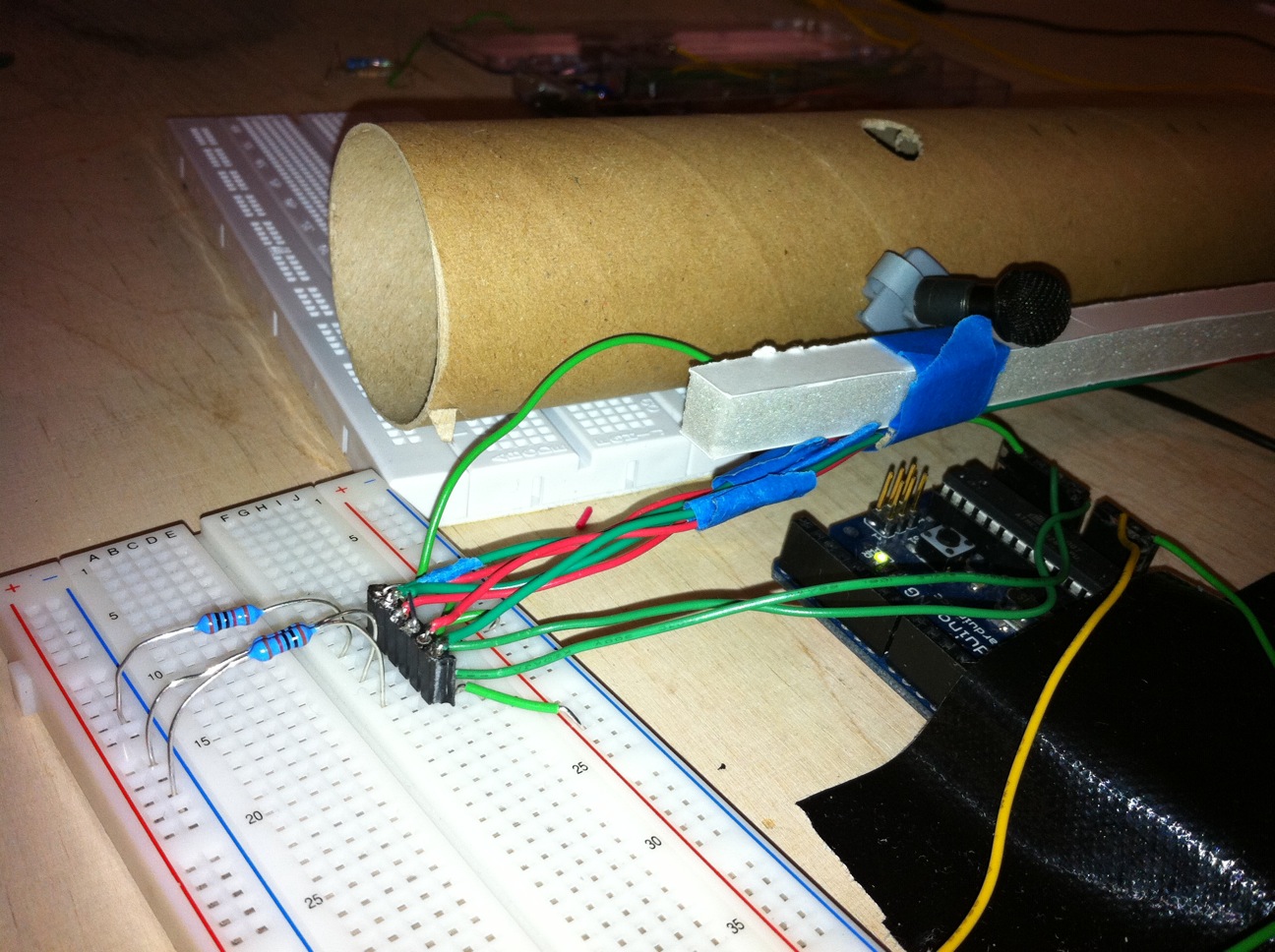
Photoresistors send analog data. Taken via Arduino send to PureData. Working great. Quite responsive.
Problem is now the mapping strategy. How can we map these processed inputs to the “song”. We were using soundfont but I guess we will map it directly to loops and control the loops with photoresistors. Mapping is still unclear.
It is the “Paja” of the University of Lapland. I was working there last spring and summer planning on what equipment to buy and testing all of the parts. I also wrote some tutorials on how to use certain sensors and other equipment with the Arduino. The part specific instructions can be found on the Equipment page. Some of them are still just dummy pages, but you can find some useful information also.
A photo-resistor controls the size of the flowers (more the light larger the size and less the light smaller the size of the flower) through Arduino over Bluetooth.
The entire thing works together (the leaves reacting to the accelerometer and flowers reacting to the light), but the is lagging too much for the flowers to respond smoothly.
The leaves fall and return back on the tree using the accelerometer sensor in the N900.
According to room’s light conditions rectangle moves left or right. If the room is bright rectangle moves to the right if the room is dark rectangle moves to the left.
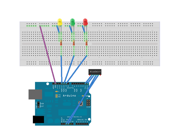
Built with Arduino and Flash. Controlled with Nokia N900 according to data coming from light sensor. Analog data is sent to N900 via BlueSMiRF Gold Bluetooth module.
This module is easy to use. It communicates to Arduino via serial communication (TX pin and RX pin) as its operating voltage is from 3.3v up to 6v.
This post describes briefly how to set and get settings of the device. You can use Zterm for Mac to send commands to the device. You basically need to enter command mode to do that from TX-O and RX-I pins.
Arduino code is also attached to test the communication over Bluetooth. The code simply return the same signals.
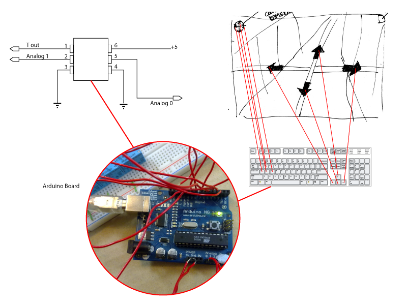
The aim is to make a more fun and physical experience linked to google street view, where the user through movement controls the direction and view of the web service. Furthermore we wanted to stir away from the traditional keys and make a dynamic and fun way to see new parts of the world: Tokyo, Los Angeles, Paris, you decide where to go!
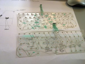
After few different concept ideas, we created an interactive controller for Google Maps. It consists of an Arduino board, an old keyboard, two kinds of sensors; accelerometer sensor – measures tilt and motion, ultrasonic sensors -measures distance and eight switches. Basically, the programme reads the values from the sensors and these control the keyboards’ pre-defined keys. The accelerometer control the camera’s pan and tilt keys(w,a,s,d), whereas, two different sensors (Ping))) ultrasonic sensor) control the horizontal movement in the the street (arrow keys).
Keyboard and sketches
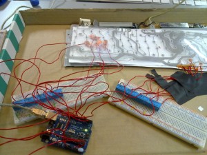
Distance measurement controlling forward, back, left and right
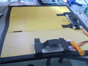
Setup: circuit between arduino and keyboard with the switches