Course project by Heidi Holm & Daniel Suominen – Designing Interaction with Electronics workshop 2009 at Mlab, Helsinki
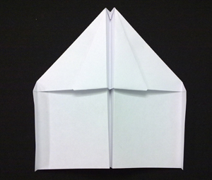
Paper Plane Pilot
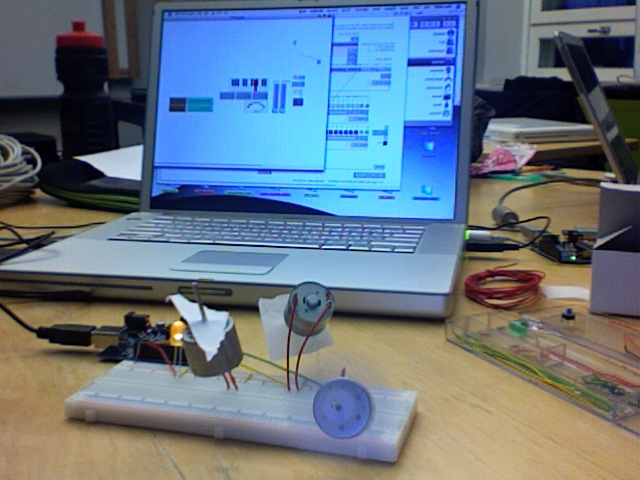
Day 1: Developing the idea. A simple game where you pilot a paper plane through the Media Lab. The controlling of the plane involves hand gestures and blowing air from your mouth. This is achieved by using accelerometer and air sensor.
Interrupts are interruptions from the main program flow triggered by some event. Interrupts are not supported by BASIC Stamp but Arduino can support it by including a library. AVR MacPack (AVR-GCC) also can support it by including <avr/interrupt.h>. Interrupts is very useful function because you don’t have to listen to the external event all the time in your code. If you assign the external event as interrupts, AVR jumps to particular function when the event happens and returns to current location of the code.
Bit operations are used when interfacing with digital out such as switching pins On/Off. Programming with bit operations enable following functions to control digital out.
Switching pins on (for example, turning on LED)
Switching pins off (for example, turning off LED)
Toggling pins (for example, Turning of LED if it is on and vice versa)
The aim is to create a metaphor of the digitalization of the sound, continue signal to discontinue signal, and to try to make a machine, which react with the voice’s expressivity.
Sound: the principally incoming sound is the voice.
Microphone: cardioid headband voice microphone.
Audio interface: it transforms the analog signal in digital information.
Computer (max/msp): It analyzes the information (pitch and amplitude) that comes from the interface with help of the fiddle object (Max/msp). For control and to communicate with the arduino, I use the arduino object.
Arduino board: the information that the analysis gives me, modify the number of motors that are active and the velocity of each one.
Sound object: is a small machine that consists in twelfth motors that are controlled by the input sound (voice). Each motor produces a pulse and repetitive output sound. Three of them have the possibility to control their velocity and others to control only on/off.
Sound: the pulse and repetitive sound is created by each motor with a propeller touching a fix material in each rotation.
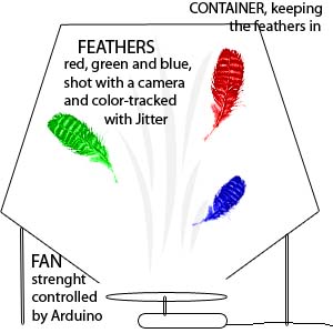
My new project plan goes as follows. I have a fan blowing air into a transparent container with feather of different color (say, red, green and blue). The movement of these feathers is then shot with a video camera or a webcam and color-tracked with Jitter. The data of the X-Y movement of each feather is then mapped to drive sound (2 control parameters per feather = 6 in total). To make it more interesting, the fan should be controlled by Arduino as well. I could drive the fan with a semi-random algorithmic data to make the whole thing a self-containing alive entity or, say, control it with a midi controller for a sound performance. Or the fan could be indirectly controlled by the feathers movement to introduce some feedback to the system. Furthermore, I could make the system more interesting by having several fans to create different turbulent fields.So, how easy is it to control a fan with Arduino? Would the small motors we have be powerful enough to operate as a fan (if I build a fan blade for example from cardboard) or should I buy ready fans?The color tracking works already, I’ve tested it. I should just 1.) obtain a fan 2.) obtain feathers 3.) obtain materials to build a container for the feathers and build it, 3.) figure out how to control the fan with Arduino and 4.) build a sound-making instrument and map the paramaeters in a musical way.Comments, suggestions?
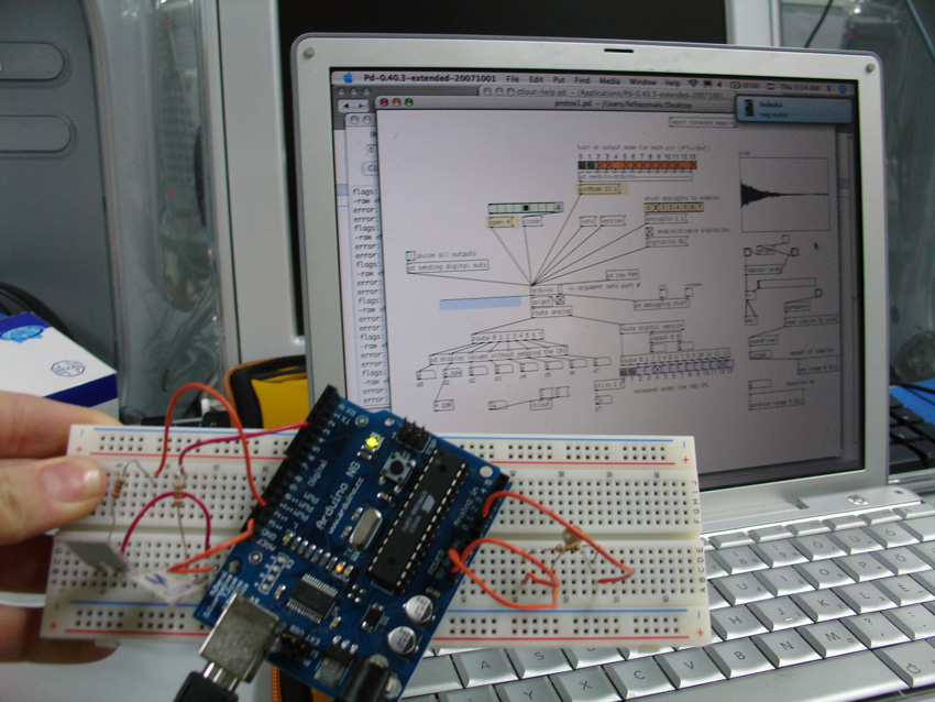
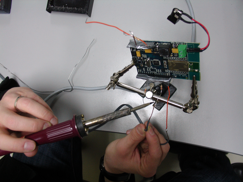
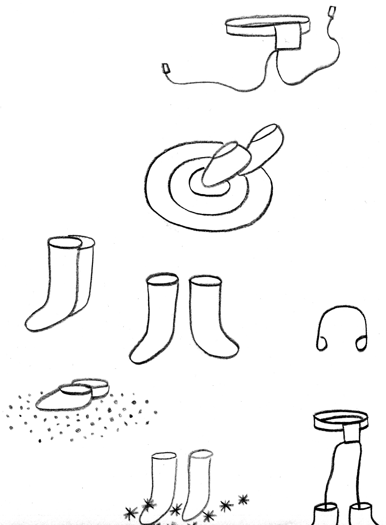
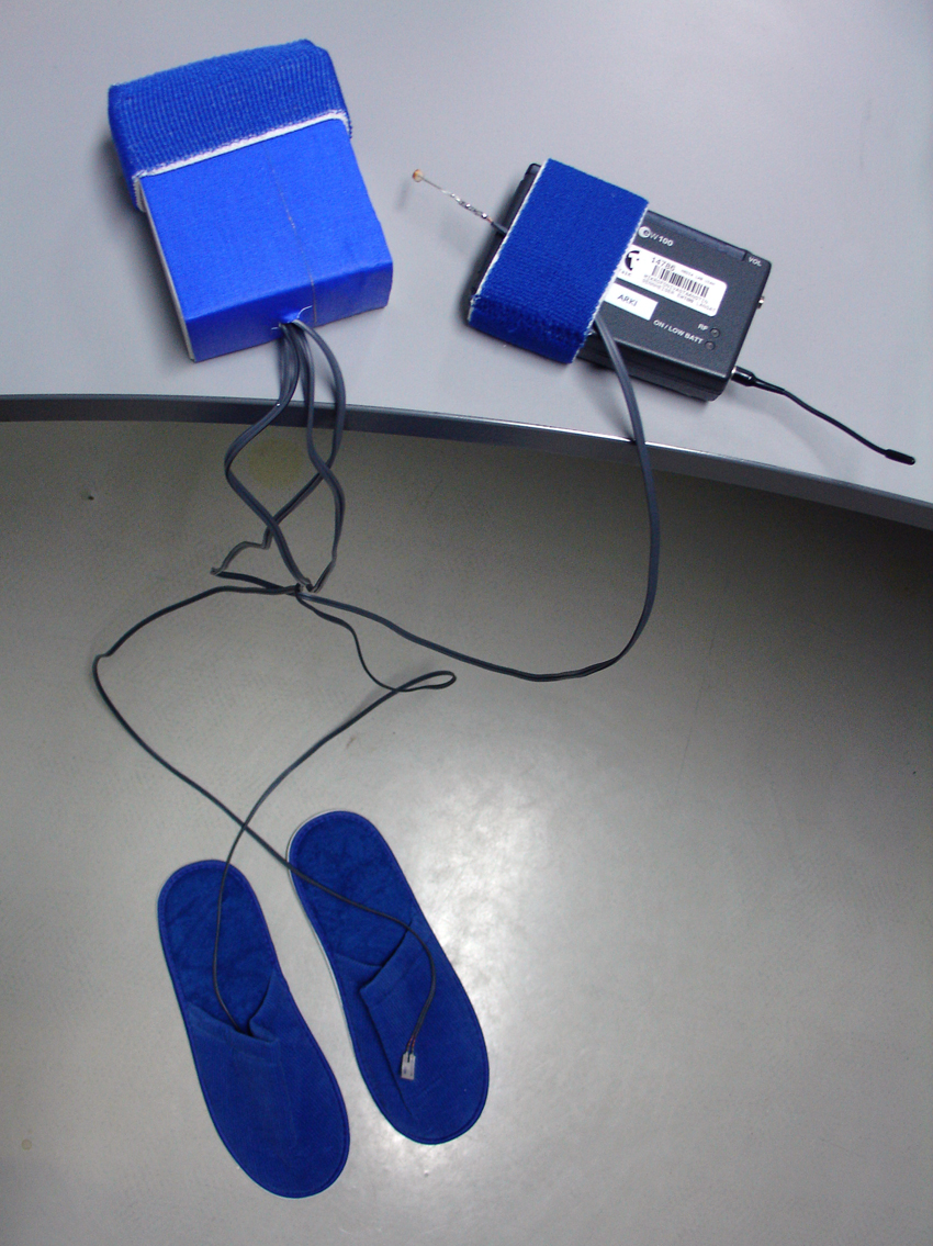
A prototype by Markku Ruotsalainen, Jenna Sutela and David SzauderMood Shoes are sonic wearables for super walking. They enable a ubiquitous (mobile) way to experience the environment in a manner of choice. Wearing Mood Shoes, one can decide whether to walk on thin ice, on the beach, in a puddle, in snow, on the moon or on the foil of a big drum regardless of the nature of their actual location/environment. The sense of ground varies from grains of sand to splashes of water expressed through sound samples in headphones.The first step‘ {$STAMP BS2}’ {$PBASIC 2.5}pLED PIN 12pLED PIN 15pSens PIN 0′ ====[ Variable]=============================wBuf VAR WORD’====[Initialization]============================DEBUG CLS, “start”, CR’====[Main]================================xMain:DOPULSIN pSens, 1, wBufDEBUG DEC wBuf, CRIF wBuf > 200 THENPULSOUT pLED, 1PULSOUT pLED, 100ELSEPULSOUT pLED, 0PULSOUT pLED, 1000ENDIFLOOPENDSwitching from BASIC Stamp to ArduinoArduino andPureDataAssemblingAn early adaptorSketchingProject outlineBuildingEquipment- Arduino board- 2 touch sensors- 1 light sensor- Bluetooth- Pure Data- Sound samples- Shoes, belt- Headphones- FM receiver and transmitter (see http://anarchy.k2.tku.ac.jp/)ProgrammingTasks:1) Realizing a (Bluetooth) connection between Arduino board and PureData- MIDI from BS to PD2) Making the touch and light sensors work with Arduino and shoes3) Connecting the FM receiver and transmitter and the headphones to the systemInterfacingTasks:1) Collecting sound samples2) Choosing atmosphere samples to work with the light sensor3) Placing the touch sensors in shoes and attaching the Arduino board to a beltTry me!
Nov 10, 2007Comments Off on Pulse IO for Ping))) Ultrasonic Sensor
PBasic code for Ping))) Ultrasonic Sensor looks very simple.
BASIC Stamp PBasic code:
pPing PIN 7 ‘ 7 pin connects to SIG pin of the PING)))
wTime VAR WORD ‘ declaring wTime as a variable
cTrigger CON 5 ‘ trigger pulse = 10 uS for BS2
DO ‘ repeat between DO – LOOP PULSOUT pPing, cTrigger ‘ send a command to Ping))) PULSIN pPing, 1, wTime ‘ receive a value from Ping)))
DEBUG DEC5 wTime, CR ‘ send the value to computer
PAUSE 100 ‘ stop for 100 milliseconds
LOOP
If you are not familiar with BS, you can only look at Pulsin and Pulsout. Once BS sends a Pulse for a certain period. The period seems 50µs. The Ping))) sensor send back the value after that.
Pulseout command:
PULSOUT Pin, Period
Pin is a variable/constant/expression (0 – 15) that specifies the I/O pin to use. This pin will be set to output mode.
Period is a variable/constant/expression (0 – 65535) that specifies the duration of the pulse. The unit of time depends on the microcontroller. in my case, a unit is 10µs.
PULSIN Pin, State, Variable
Pin is a variable/constant/expression (0 – 15) that specifies the I/O pin to use. This pin will be set to output mode.
State is a variable/constant/expression (0 – 1) that specifies whether
the pulse to be measured is low (0) or high (1). A low pulse begins
with a 1-to-0 transition and a high pulse begins with a 0-to-1
transition.
Variable is a variable (usually a word) in which the measured pulse duration will be stored.
f you want to simulate this on Max/MSP via Maxduino by Marius Schebella and Arduino, You can download a PDF about the PING))) from Parallax site. Page 3 would be helpful to understand the pulse.
The concept involves defining discrete regions of space between 2
‘pads’ (preferably small patches that can be attached to the body). Data is controlled in intervals by the proximity between 2 objects increasing and decreasing.
For instance, instead of the continuous stream of data from a source
such as a Theramin, there would be defined regions of space which
would trigger a discrete sequence of a defined (musical) scale.
The user would not be touching the pads but the signals would be triggered by the pads moving closer to one another or farther apart. One scenario is that a person would have one attached to their hand and one to the top of their foot – and there would be a range of intervals that would be triggered between the closeness of the hand and foot.
Working Plan / Technical Solutions
The proximity sensor, PING Ultrasonic, communicates with BASIC Stamp and MAX/MSP via Arduino Bluetooth.
A program defines the distinct regions between the pads.
As project for the physival computing course I´d like to realize a “robotic orchestra”. The basic idea is to control several motors that are connected to the computer via an Arduino board. The actions of these motors is controlled creating a Pure Data patch. The motors serve like “real world players”. They can play and “bang” respectively on all kinds of objects according to the control data they receive from the host software. Digital bits and bytes are transferred into real motions.
I´ve seen a couple of people using solenoid motors for similar purposes, so this might be one direction to start with.
The working title of my project is I Can. This might be regarded as the can equivalent of I, Claudius, in the sense that it has something to do with I-dentity. The idea is to make a musical instrument out of a beer can and discover what its potential for sonic performance might be (er). If a performance is forthcoming, it will surely have something to do with the metaphor of ease vs. effort, i.e. the I Can constrasting with the I Cannot. In any case, the can will have to have some life of its own, otherwise it will not be its own I.
I would like to put a wireless Arduino inside, along with a battery box, some sensors and a servo motor to make the beer can shake (rhythmically?) on command from the remote computer. What sensors CAN I put inside? Perhaps touch, velocity, orientation, a microswitch to detect whether the ring cap is in place or lifted.
What sounds will I control with it? Maybe Offenbach’s Can-Can. OK, as yet I have no idea.
The programming of the beer belly to go with the instrument is another long term project. More on that when I know how many beers I had to drink before I found the ideal can for the prototype.
Wondering today about how new ways of communication, allowed by our present time technology, affect human identity transformation and construction in the net and how they can cause physical feeling and human energy perception to be lost or experienced in a new manner, nickname: persona project is an interactive audiovisual installation where people is obligated to act to make the piece possible and wants to make them wonder about the kind of relationship established between them and how they are showing their identity to the others;
The work would consist of taking data from visitors’ bodies by sensors, which would manipulate the sound and taking snapshots of their faces to build a new face with all of them. Sound and image would be streamed to a website.
Development (working plan):
During the following three month:
1. Make some tests with sensors to experience the kind of data that we can receive from the human body and decide the kind of relation that it can be established between them and the sound of the installation.
2. Make some test about the disposition of the sensors and how the visitor must use them.
3. Decide the shape of the presentation of this part of the project and also the whole project output.
Technical solutions:
Sensors (undefined)
Arduino
Max/MSP
Questions:
Are there some sensors that I could test before buying them? I’m interested in blood pressure, body temperature, sweat, heat beating, nervous system… any other ideas?
Apr 11, 2007Comments Off on Controlling servos with Motion Sensor
At the beginning me and Linus Roune both had a go at controlling Servos with some sort of data we would get form a sensor. Linus got into some heavy stuff with Arduino I went to look for solution using Basic Stamp.
The servos we had were Parallax (Futaba) Servos so hooking them with Basic Stamp was easy, and I found the code on the web. What I didn’t pay attention to was the difference between Standard and Continuous Rotation type of servo.
This is an educational work where children (and adults) can learn how to clean a floor with a vacuum cleaner. Inside the vacuum cleaner is a light sensor connected to Arduino-microcontroller, which is connected to Processing-software. The light sensor recognized white spots from the floor (made out of a computer display) and cleans it if one is fast enough, if not the spot get stuck.
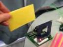
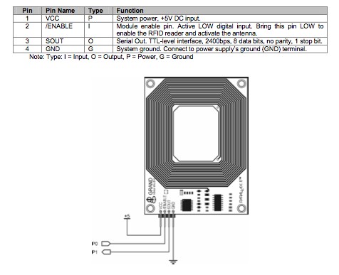
You can use Parallax RFID reader module to identify object from a large set by hiding RFID card inside it. Basically reader has two signal pins, one out and one in. First is used to enable/disable reading, second is used for reading the card identification number.


 My new project plan goes as follows. I have a fan blowing air into a transparent container with feather of different color (say, red, green and blue). The movement of these feathers is then shot with a video camera or a webcam and color-tracked with Jitter. The data of the X-Y movement of each feather is then mapped to drive sound (2 control parameters per feather = 6 in total). To make it more interesting, the fan should be controlled by Arduino as well. I could drive the fan with a semi-random algorithmic data to make the whole thing a self-containing alive entity or, say, control it with a midi controller for a sound performance. Or the fan could be indirectly controlled by the feathers movement to introduce some feedback to the system. Furthermore, I could make the system more interesting by having several fans to create different turbulent fields.So, how easy is it to control a fan with Arduino? Would the small motors we have be powerful enough to operate as a fan (if I build a fan blade for example from cardboard) or should I buy ready fans?The color tracking works already, I’ve tested it. I should just 1.) obtain a fan 2.) obtain feathers 3.) obtain materials to build a container for the feathers and build it, 3.) figure out how to control the fan with Arduino and 4.) build a sound-making instrument and map the paramaeters in a musical way.Comments, suggestions?
 The first step‘ {$STAMP BS2}’ {$PBASIC 2.5}pLED PIN 12pLED PIN 15pSens PIN 0′ ====[ Variable]=============================wBuf VAR WORD’====[Initialization]============================DEBUG CLS, “start”, CR’====[Main]================================xMain:DOPULSIN pSens, 1, wBufDEBUG DEC wBuf, CRIF wBuf > 200 THENPULSOUT pLED, 1PULSOUT pLED, 100ELSEPULSOUT pLED, 0PULSOUT pLED, 1000ENDIFLOOPEND
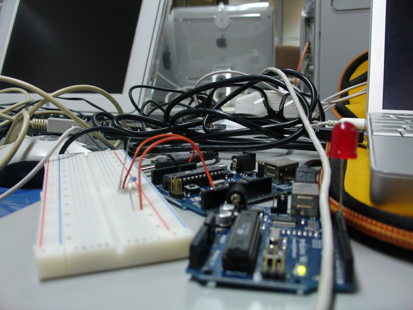


