Mood shoes by Markku Ruotsalainen, Jenna Sutela and David SzauderGimme Sugar by Anna Keune and Jari SuominenGrid Shuffling by Keri Knowles and Abhigyan SinghThe Sixth Sense by Kimmo Karvinen and Mikko ToivonenHugiPet by Juho Jouhtimäki and Elise LiikalaDigital Painting Control by Juho Jouhtimäki, Kimmo Karvinen and Mikko ToivonenTwinkling Gloves by Anne Naukkarinen, Pekka Salonen and Kristine VisanenFurry Modulator by Atle Larsen and Mikko Mutanen
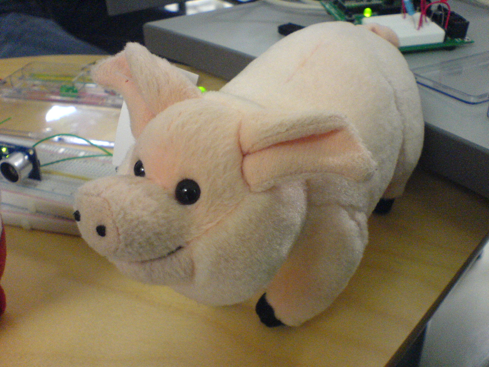
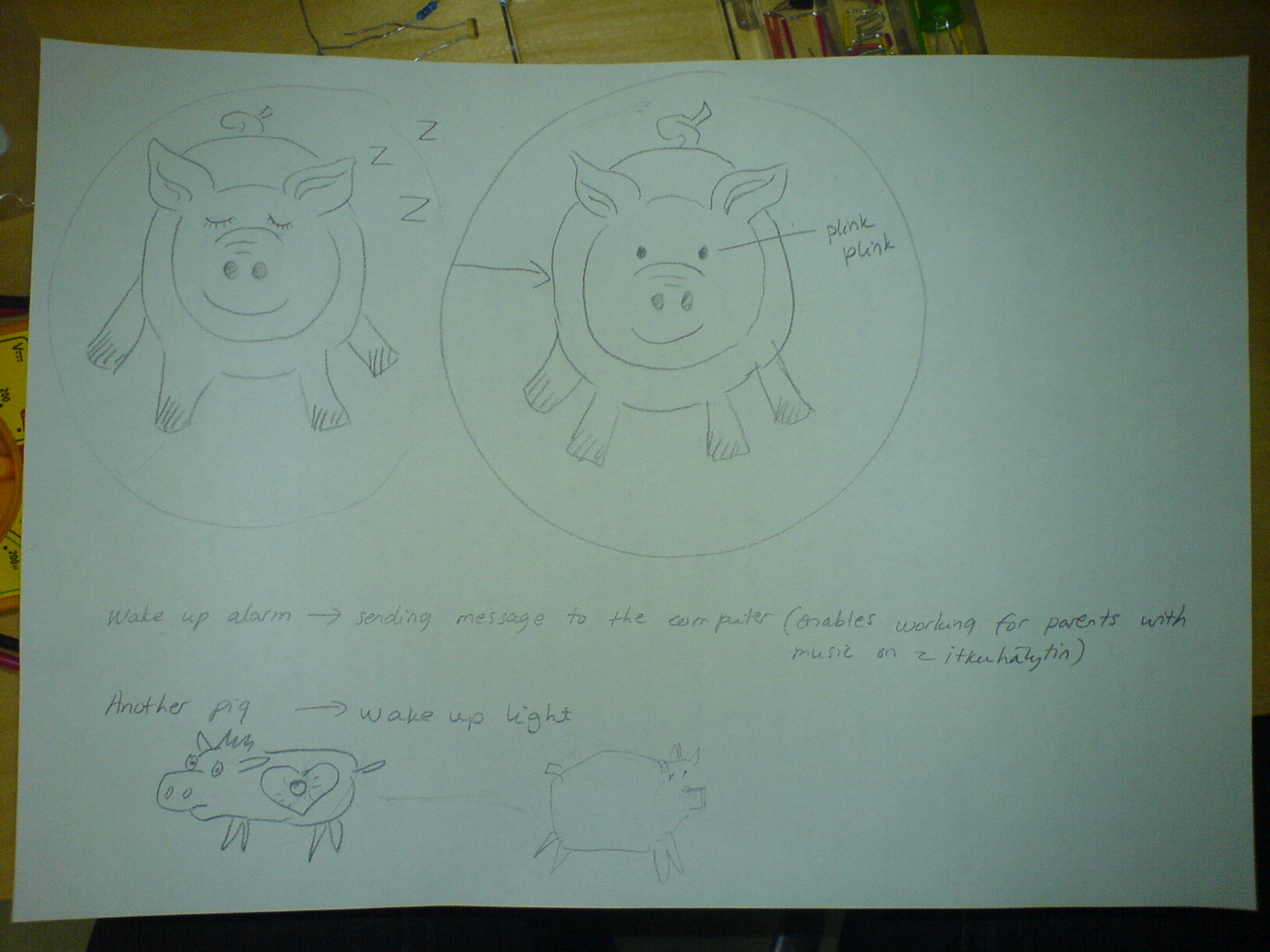
Protected: HugiPetMonday, November 12th, 2007HugiPets are a way to connect people. HugiPets are connected via network and if you hug yours your friends HugiPet reacts.We use Air v1.1 (Air sensor) to measure pressure and and send the signal to other HugiPet via network. Hugging light the other HugiPets led and shows how hard you are pressing.Workgroup: Elise Liikala, Mikko Toivonen, Kimmo Karvinen ja Juho Jouhtimäki.November 13th, 2007 at 4:20 pmPigs talk.HugiPet project went on today when we operated with the pets we bought. It was time for surgery. There was a sound when squeezing the warthog and we wanted to know how it is done. We found a little bag filled with air and a pipe. Very simple mechanic using airpressure. The other pig will be filled later with some kind of pressure detecter too + the sensor. We are not sure at this point if we are using the original soundmechanics from warthog in some way also.November 14th, 2007 at 11:18 pmToday the hugipet project was experiencing with sensors. But what we found out was that there was not that kind of sensor available in our course material which we would have needed. The idea of hugging a pet and using air sensor was changed to motion based sensor. In the end of the day we had created a new brilliant ideaThe idea:To make a toy which will send information to computer and to another pet when moved. To find out more specific use of this toy, you will have to wait until Friday So exciting…November 15th, 2007 The pig-animation was drawn and created today. Also to wires were soldered and code tested. Pigie’s tummy got new filling. It was time for testing.November 16th, 2007 The coding project of HugiPet still needed some effort today. Juho copep with it right on time before our presentation. Our non-sonic baby alarm was well and funtioning!This is how the HugiPet works:The child has a toy next to her/him in bed which recognizes movement in x- and y-axis. When the child wakes up and starts to move the toy, there will be signals sent to computer. On computer there is an icon which shows a simple animation of a sleeping piggie. When child wakes up, the animation icon will visually change and the piggie wakes up (+ makes an oink oink sound). If the toy is not moving for a while, the piggie falls asleep again.This application works better then the traditional baby crying alarm in cases wherea) a parent is working for example in a place where there is a lot of other sounds so one may not hear the alarmb) it gives an opportunity to listen for example music when working with one’s laptop while the child is sleeping on balconyc) It can be a very helpfull device for deaf people who can’t hear their baby cryingThe next phase would be to make another toy or an object which reacts to the movement of piggie. In that case you wouldn’t have to be looking at the computer all the time.
Project and copyright by: Kimmo Karvinen, Juho Jouhtimäki and Mikko Toivonen.
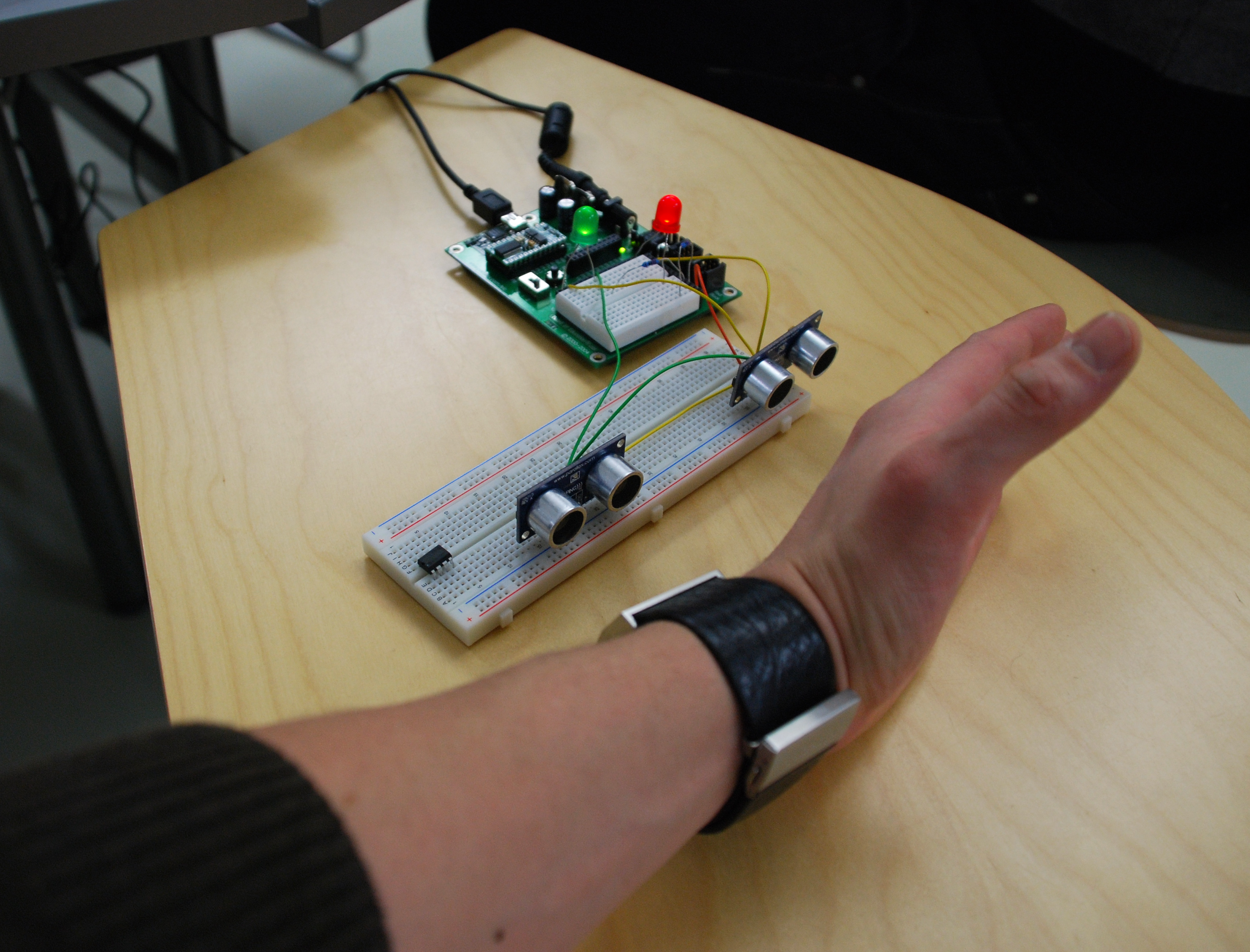
Idea is to enhance digital painting frame (laptop framed and turned to wall mounted slideshow) with a feature that makes it possible for user to swap images by moving hand left or right in front of the frame.
We use two Ultrasonic Sensors to detect which way users hand is moving. The actual slide show will be made with flash.
Edit. We didn’t get the flash to work with serial data so now project works with director with embed Flash.
Inputs
-distance
-sectors in the visual field
-ripple gestures
Processing
-movement through the sectors and steps builds up a sequence
-making a ripple gesture triggers a chain reaction of samples in the stack
-also a single sample can be triggered
-distance affects the volume and pitch of the ambient background tone
-a combination of distance and spatial grid selects a sample from the pool
-temporal effects on volume and filtering for the samples in a chain reaction
Outputs
– MIDI events into Reason (possibly)
– samples loaded inside PD
– stereo sound through loudspeakers
Interface
Bodily movement in space for a single person using 2 hands and ripple gestures controlling speed, pitch and the triggering of (stacked) sample sequences.
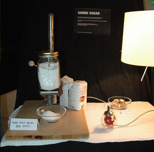
Depending on the angle of tilting an object, shaped like a sugar shaker, a bowl placed elsewhere is opening and dispensing sugar. The more you shake/tilt the object the more sugar will be dispensed. This could be a fun way to sweeten a beverage or represent how much attention in form of sugar one gives to a significant other.
Proximity sensors or touch sensors will be arranged behind a horizontal panel controlling a grid of objects (for example, images) displayed on a computer screen.
There will be intutive mapping between the objects on the screen & the physcial panel on the table. User can select an object, move it to another location & place it on the new location using his/her hand’s gestures & movement over the panel. He would also be able to see simlutaneous reflection of change on the computer screen.
Working:
A section of the panel senses if an object is to be selected by the hand being at the closest proximity. By making the gesture of grabbing and pulling away, the increased distance from the area registers that the object in the section is selected and being moved, causing the other sections to switch into a receptive state. The object may be dropped in any of the other sections, swapping it with the previous one, and possibly reshuffling the whole arrangement.
Team: Keri & Abhigyan
Nov 12, 2007Comments Off on Argumented Reality Game
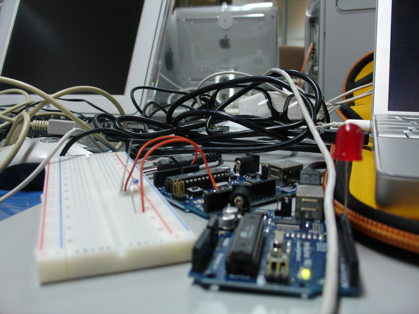
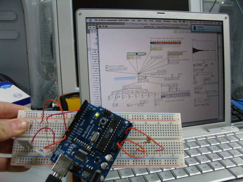
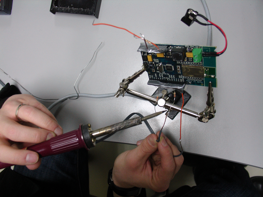
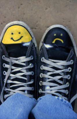
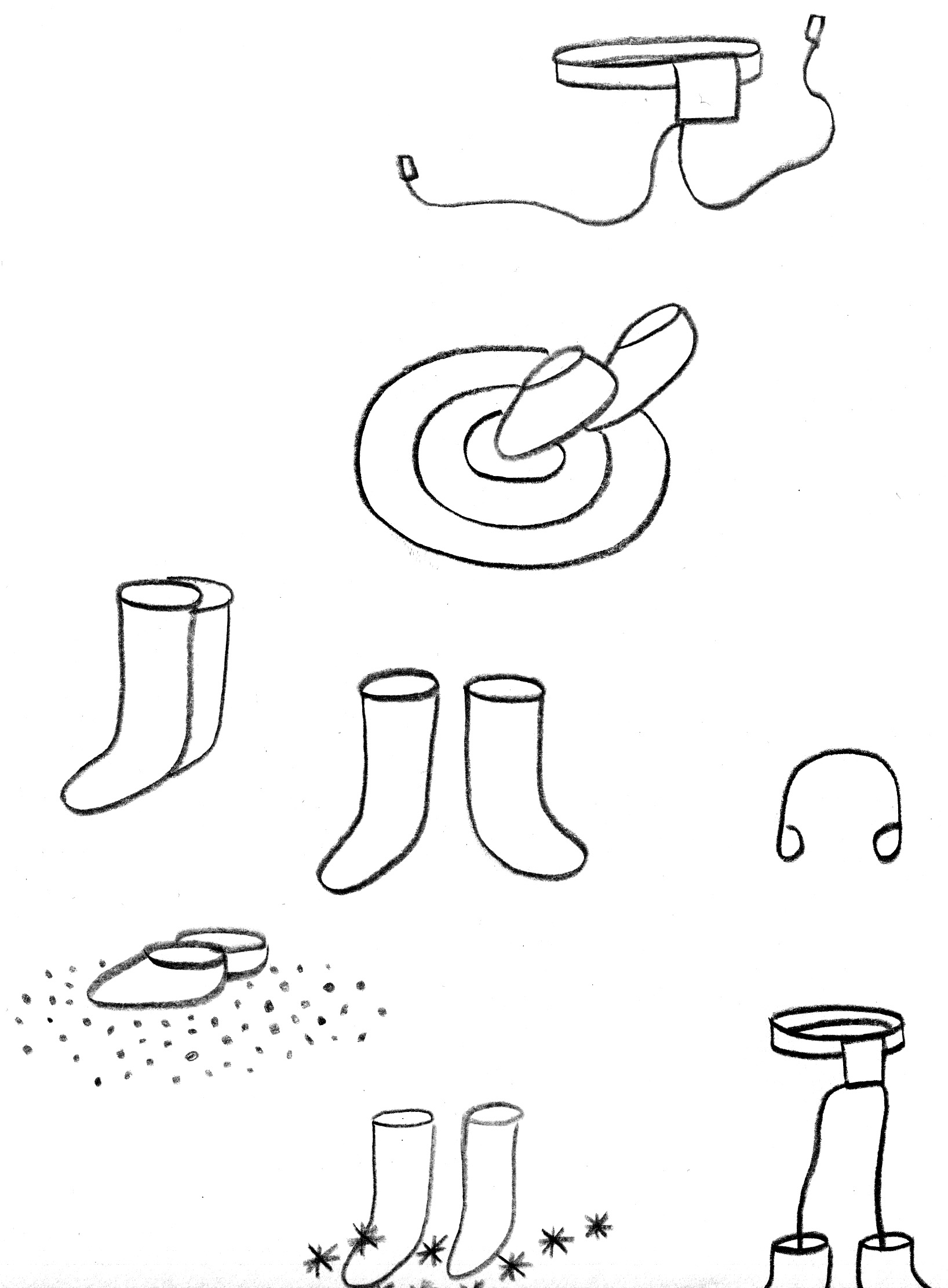
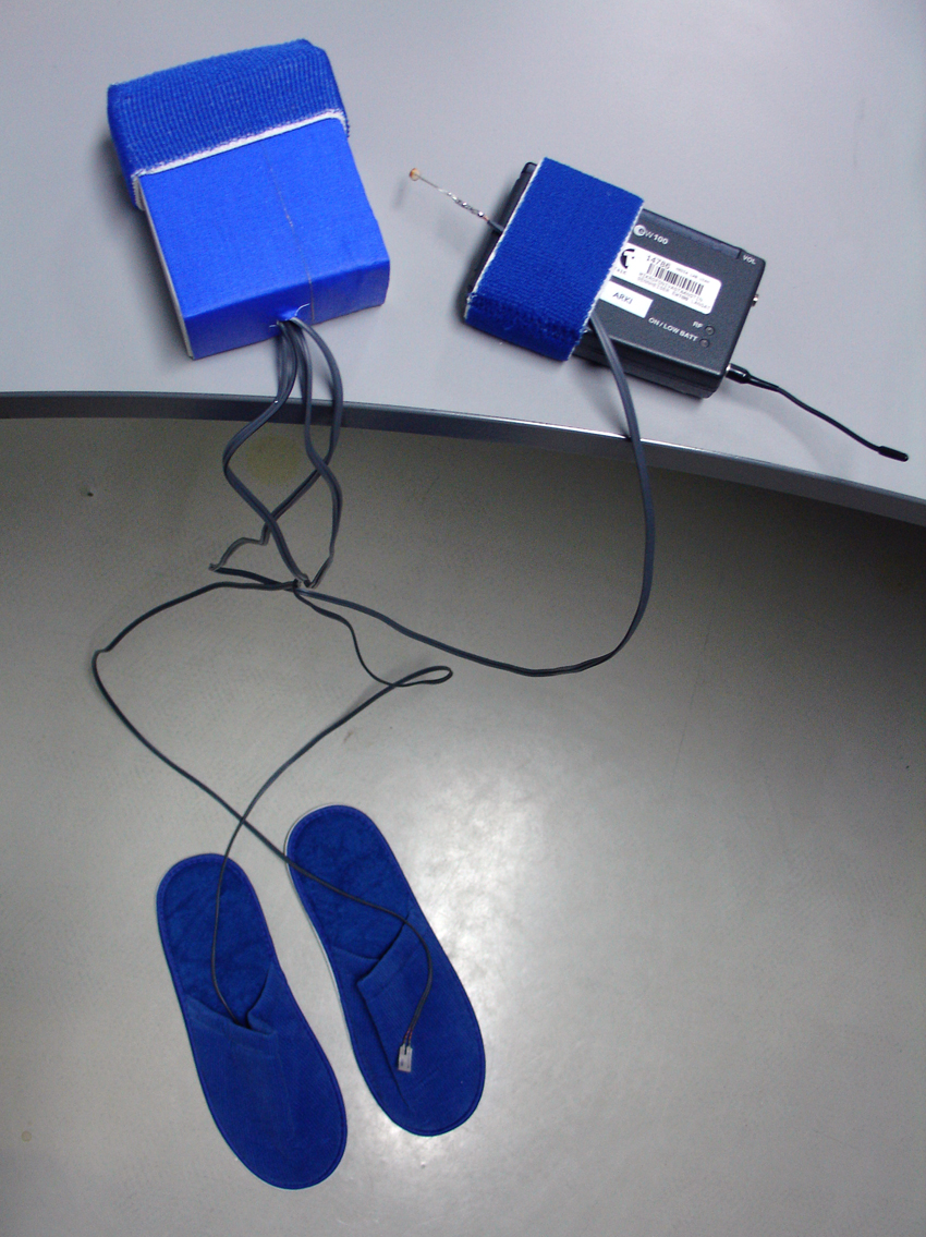
A prototype by Markku Ruotsalainen, Jenna Sutela and David SzauderMood Shoes are sonic wearables for super walking. They enable a ubiquitous (mobile) way to experience the environment in a manner of choice. Wearing Mood Shoes, one can decide whether to walk on thin ice, on the beach, in a puddle, in snow, on the moon or on the foil of a big drum regardless of the nature of their actual location/environment. The sense of ground varies from grains of sand to splashes of water expressed through sound samples in headphones.The first step‘ {$STAMP BS2}’ {$PBASIC 2.5}pLED PIN 12pLED PIN 15pSens PIN 0′ ====[ Variable]=============================wBuf VAR WORD’====[Initialization]============================DEBUG CLS, “start”, CR’====[Main]================================xMain:DOPULSIN pSens, 1, wBufDEBUG DEC wBuf, CRIF wBuf > 200 THENPULSOUT pLED, 1PULSOUT pLED, 100ELSEPULSOUT pLED, 0PULSOUT pLED, 1000ENDIFLOOPENDSwitching from BASIC Stamp to ArduinoArduino andPureDataAssemblingAn early adaptorSketchingProject outlineBuildingEquipment- Arduino board- 2 touch sensors- 1 light sensor- Bluetooth- Pure Data- Sound samples- Shoes, belt- Headphones- FM receiver and transmitter (see http://anarchy.k2.tku.ac.jp/)ProgrammingTasks:1) Realizing a (Bluetooth) connection between Arduino board and PureData- MIDI from BS to PD2) Making the touch and light sensors work with Arduino and shoes3) Connecting the FM receiver and transmitter and the headphones to the systemInterfacingTasks:1) Collecting sound samples2) Choosing atmosphere samples to work with the light sensor3) Placing the touch sensors in shoes and attaching the Arduino board to a beltTry me!
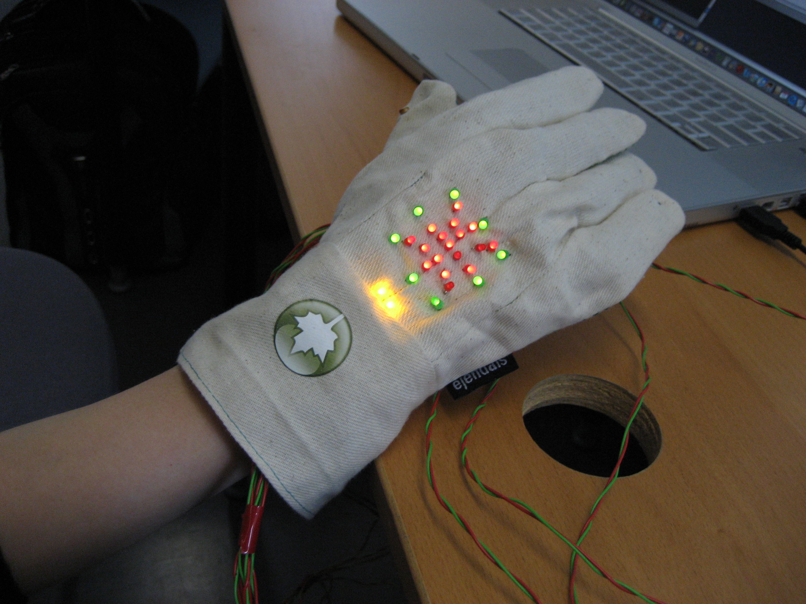
First we played with facial expression detection and so forth. Taping sensor to for example to the eye brows to see that amount of surprise from their angle and position. Basically lots of tape in the face.One would express emotions etc with lights. You’d have the light bulb head for those Eureka moments.We ended up going with pairs of mittens. Lots of possibilities there.0 hands mode (mitten alone):
Thermometer, mitten alerts when it’s cold: take me with you!
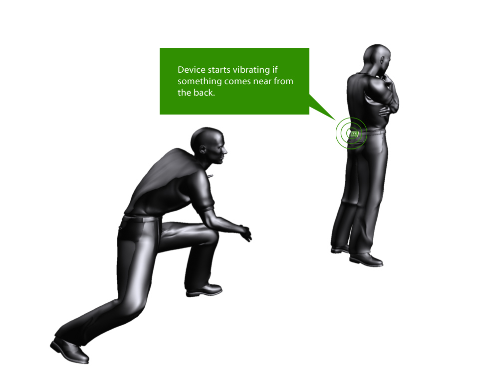
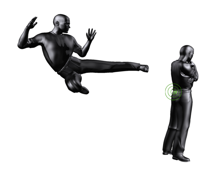
Project and copyright by Kimmo Karvinen and Mikko Toivonen
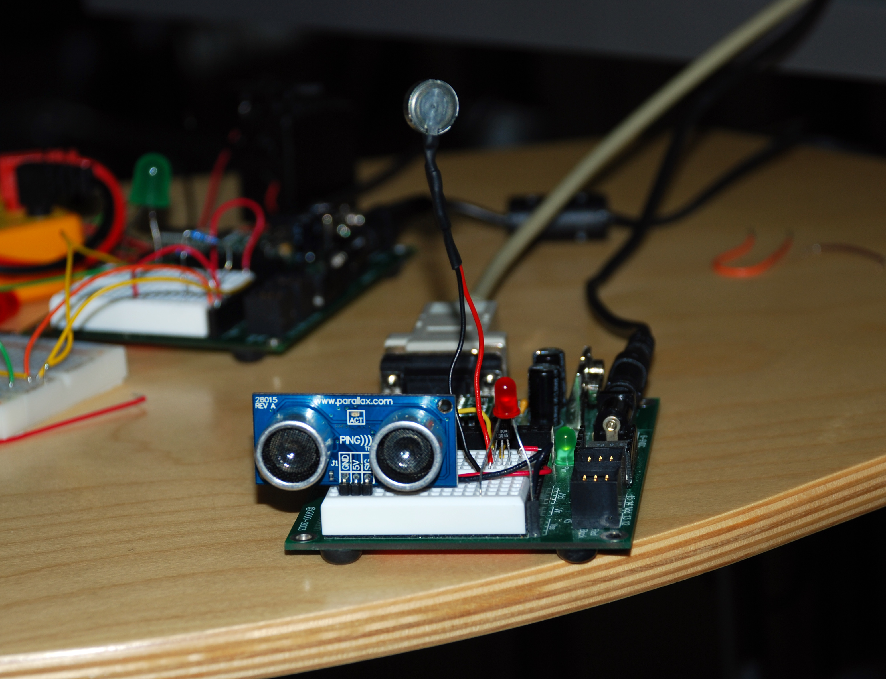
the sixth sense is a device that warns user when someone or something is approach from the back (range is set to 2,5 meters). It’s attached to belt so that the Ultrasonic Sensor is on the other side and the vibration motor is near the skin.
More info: kimmo.karvinen@taik.fi
Nov 10, 2007Comments Off on Pulse IO for Ping))) Ultrasonic Sensor
PBasic code for Ping))) Ultrasonic Sensor looks very simple.
BASIC Stamp PBasic code:
pPing PIN 7 ‘ 7 pin connects to SIG pin of the PING)))
wTime VAR WORD ‘ declaring wTime as a variable
cTrigger CON 5 ‘ trigger pulse = 10 uS for BS2
DO ‘ repeat between DO – LOOP PULSOUT pPing, cTrigger ‘ send a command to Ping))) PULSIN pPing, 1, wTime ‘ receive a value from Ping)))
DEBUG DEC5 wTime, CR ‘ send the value to computer
PAUSE 100 ‘ stop for 100 milliseconds
LOOP
If you are not familiar with BS, you can only look at Pulsin and Pulsout. Once BS sends a Pulse for a certain period. The period seems 50µs. The Ping))) sensor send back the value after that.
Pulseout command:
PULSOUT Pin, Period
Pin is a variable/constant/expression (0 – 15) that specifies the I/O pin to use. This pin will be set to output mode.
Period is a variable/constant/expression (0 – 65535) that specifies the duration of the pulse. The unit of time depends on the microcontroller. in my case, a unit is 10µs.
PULSIN Pin, State, Variable
Pin is a variable/constant/expression (0 – 15) that specifies the I/O pin to use. This pin will be set to output mode.
State is a variable/constant/expression (0 – 1) that specifies whether
the pulse to be measured is low (0) or high (1). A low pulse begins
with a 1-to-0 transition and a high pulse begins with a 0-to-1
transition.
Variable is a variable (usually a word) in which the measured pulse duration will be stored.
f you want to simulate this on Max/MSP via Maxduino by Marius Schebella and Arduino, You can download a PDF about the PING))) from Parallax site. Page 3 would be helpful to understand the pulse.
I made a list of the components can be used with Pudino and Maxduino patch but not all of them have been tested. I will update when I found new components compatible with the patches.
The concept involves defining discrete regions of space between 2
‘pads’ (preferably small patches that can be attached to the body). Data is controlled in intervals by the proximity between 2 objects increasing and decreasing.
For instance, instead of the continuous stream of data from a source
such as a Theramin, there would be defined regions of space which
would trigger a discrete sequence of a defined (musical) scale.
The user would not be touching the pads but the signals would be triggered by the pads moving closer to one another or farther apart. One scenario is that a person would have one attached to their hand and one to the top of their foot – and there would be a range of intervals that would be triggered between the closeness of the hand and foot.
Working Plan / Technical Solutions
The proximity sensor, PING Ultrasonic, communicates with BASIC Stamp and MAX/MSP via Arduino Bluetooth.
A program defines the distinct regions between the pads.
A “foot controller†of audio synthesis. Sort of “track pad†sensible to the position and pressure to be played by the foots.
Technical solutions : Big Pressure sensors (5 or 6) can be placed under a “mat†flat surface (20cm, 20cm) to give information in an axis system (x y z?) for MAXMSP or PD.
In short the idea is to use chemical reactions as control data. Here the key question is: what kind of parameters can one measure in a liquid? A few that have come to my mind: salt level (conductivity?), temperature etc. I’m sure there are others…
This control data would be mapped to generate and/or modify sound. The idea is to create a performative composition with little direct user intervention, although it might be necessary to work as a cook and mix in different ingredients during the performance and change the temperature of the substance.
The working title title for my project is “soundtrack of our life”. The idea for this project derives for one of my earlier works. A sound installation for an mp3 player: where the viewer/ listener was offered an ipod set to play a huge amount of various samples on random. Changing the experience of the surrounding by changing the sound scape. This time i would like it to be possible for the sound to change because of the listeners actions/movements.
Sensor input would change the sound. Ideally the user should be able to carry the set around.
Technical solutions are something where i only have some vague ideas at the moment. I do think that i need a sound source, sensors and a micro-controller that communicates with them both.
As project for the physival computing course I´d like to realize a “robotic orchestra”. The basic idea is to control several motors that are connected to the computer via an Arduino board. The actions of these motors is controlled creating a Pure Data patch. The motors serve like “real world players”. They can play and “bang” respectively on all kinds of objects according to the control data they receive from the host software. Digital bits and bytes are transferred into real motions.
I´ve seen a couple of people using solenoid motors for similar purposes, so this might be one direction to start with.

 The first step‘ {$STAMP BS2}’ {$PBASIC 2.5}pLED PIN 12pLED PIN 15pSens PIN 0′ ====[ Variable]=============================wBuf VAR WORD’====[Initialization]============================DEBUG CLS, “start”, CR’====[Main]================================xMain:DOPULSIN pSens, 1, wBufDEBUG DEC wBuf, CRIF wBuf > 200 THENPULSOUT pLED, 1PULSOUT pLED, 100ELSEPULSOUT pLED, 0PULSOUT pLED, 1000ENDIFLOOPEND